3
1. Indoor Unit
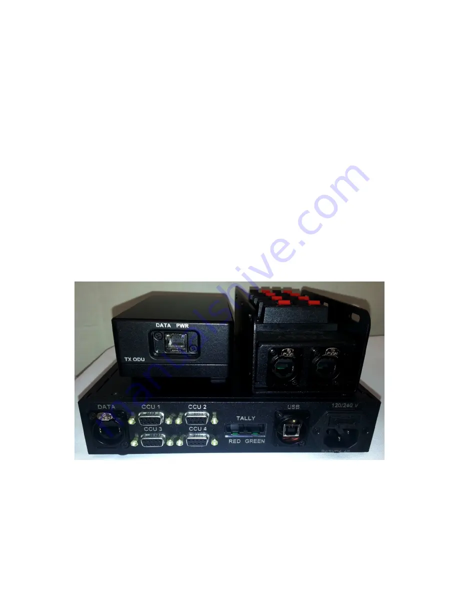
1.1 Connections
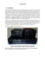
The RCP-TX-IDU should be situated in a suitable place to gain access to the front panel
when required. The RCP-TX-IDU should be connected to the TX ODU using Cat 5 or 6
data cable (not supplied). There are four DB-9 pin female ports on the rear panel; they
are labelled CCU1 to CCU4. The port number relates to the Camera RCP ID that will be
connected to the RCP-TX-IDU. Example; a panel connected to port number 1 will have
a system ID of 1. Up to 4 panels can be connected at any one time to control a
maximum of 4 independent cameras. In the case of the Sony control panel, the ID/Port
number will be indicated on the panel in the Tally Display area.
Camera tally are interfaced via the camera tally interface. Connectivity between the
camera tally interface and the RCP-TX-IDU are Cat 5 or 6 ethernet cable connection the
Red and Green Tally respectively. The video switch tally control (contact closure) is
connected to Red and Black ‘Push Terminal’ tabs on the Tally interface unit.
AC power is applied to the RCP-TX-IDU.
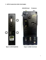
Figure 4. Three Camera Control Unit Paint components
Note: Not pictured is the Fourth component of the system is the AXTX1 Broadcast
Camera Transmitter with Camera Paint Data Receiver.


