background image

SPEEDLAN 4100 & 4200 Installation and Operation User Guide


Analyzing Wireless Equipment

13-3


Analysis Polling Interval 

Use the feature to set the rate at which the SPEEDLAN Configurator polls the brouter during analysis. 
Note that you must scan the brouter before setting the interval rate. 

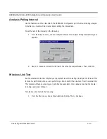
To set the rate of the interval, do the following: 

1

From the 

Analyze

 menu, choose 

Analysis Interval

. The Analysis Polling Interval dialog box 

appears. 

2

Use your mouse and move the interval to the rate of your specification. Then, click 

OK

Wireless Link Test 

Run the wireless link test to verify that your equipment is communicating properly at the RF level. This 
test can be performed when you are performing a bench test for the brouter or from the actual link. 
This process will help you during your performance evaluation. If you already scanned the brouter 
(or bridge pair), skip to Step 5. 

To initialize a link test, do the following: 

1

From the 

File

 menu, choose 

Open Remote Config

. Then, click 

Scan

Summary of Contents for SPEEDLAN 4100

Page 1: ...PEEDCOM Wireless Company 1748 Independence Blvd C 5 Sarasota FL 34234 941 358 9283 www speedlan com SPEEDLAN 4100 4200 Installation and Operation User Guide Version 1 0 Last Revised September 2000 Wav...

Page 2: ...e liable for errors contained herein or for inci dental or consequential damages in connection with the furnishing performance or use of this material Wave Wireless Networking a SPEEDCOM Wireless Comp...

Page 3: ...Rooftop and Tower Installations Warning 2 2 Package Contents 2 2 Installation Steps 2 3 Installation Diagram 2 8 Polarizations on a Grid Antenna 2 9 Vertical Polarity Horizontal Polarity 2 9 Chapter...

Page 4: ...C Filtering 6 4 Advanced Features Button 6 5 Storm Thresholds Button 6 7 Tunnel Partners Button 6 8 Chapter 7 Setting Up the IP Addresses IP Host Setup 7 1 Part I Quick Overview of IP Addressing 7 2 W...

Page 5: ...ges Sent 11 16 IP Monitor 11 17 IP TCP UDP Monitor 11 20 TCP 11 20 UDP 11 22 ICMP Monitor 11 23 ICMP Messages Received 11 23 ICMP Messages Sent 11 24 Chapter 12 Tables 12 1 System Information 12 2 Bri...

Page 6: ...ocols Ethernet Addresses Appendix 1 Common Ethernet Protocols Appendix 2 Common Ethernet Vendor Addresses Appendix 4 Common Ethernet Multicast Addresses Appendix 14 Common Ethernet Broadcast Addresses...

Page 7: ...Chapter 1 Introduction...

Page 8: ...The radios use direct sequence spread spectrum with a QPSK modulation and employ 11 dB of processing gain The SPEEDLAN 4100 4200 brouters also contain transparent Ethernet bridging and IP routing as...

Page 9: ...terface SNMP and Bridge MIB IP SNMP WaveLAN IP SNMP Trap Support SNMP Access Lists SNMP Management SNMP wireless and wired link management may be administered from any Ethernet network or remotely fro...

Page 10: ...SPEEDLAN 4200 Additional Functionality for SPEEDLAN 4100 4200 RF cable loss is negligible Brouters can be mounted in more remote locations because Ethernet cable is connected to the brouters Increase...

Page 11: ...Chapter 2 Quick Start...

Page 12: ...enables a central Ethernet LAN to be connected with one or more branch office LANs A single brouter with an omnidirectional antenna may communicate with multiple brouters to create multipoint wireless...

Page 13: ...e instructions below contact Wave Wireless If you are having trouble and need a full site installation contact Wave Wireless Networking for services and fees To install the SPEEDLAN 4100 4200 do the f...

Page 14: ...aining the appropriate antenna height For extended poles additional wall brackets may be necessary c Assemble the antenna and mount it to the pole using the included U bolt antenna mounting hardware F...

Page 15: ...made connectors to fit your particular installation needs such as Pigtail 12 adapter from brouter 1 5 10 antenna cable attaches to antenna one end and to lightning arrestor other end Lighting arrestor...

Page 16: ...f electrical tape to the connector and leave approximately 3 inches of cable exposed on either side of the connector An alternative is to begin at the lowest point so the tape overlaps from bottom to...

Page 17: ...ect the RJ 45 connector on a standard Ethernet CAT5 cable to the RJ 45 port color of port is white on indoor junction box b Connect the other end of the Ethernet CAT5 cable to your Ethernet hub switch...

Page 18: ...and Operation User Guide 2 8 Quick Start Installation Diagram The diagram below displays where the main components are located All outdoor cable connections and lightning arrestors must be insulated w...

Page 19: ...dio signal radiates from the end of the antenna like a wide beamed flashlight Vertical Polarity Horizontal Polarity In order for the antennas to operate correctly the polarities must match For most ap...

Page 20: ...___________________________________________________ ________________________________________________________ ________________________________________________________ __________________________________...

Page 21: ...Chapter 3 Hardware...

Page 22: ...Components Overview of SPEEDLAN 4100 4200 Tower Mount SPEEDLAN 4100 4200 24 Coax Pigtail To Antenna To Ground Grounding Wire To Indoor Junction Box Outdoor CAT5 Cable Lightning Arrestor Mounting Pole...

Page 23: ...ser Guide Hardware 3 3 Front and Back of Indoor Junction Box Bottom View of SPEEDLAN 4100 4200 To LAN To SPEEDLAN Chassis To AC DC Power Supply White Orange Waterproof Ethernet Bulkhead Connector Ethe...

Page 24: ...enu select Open Config Then select the appropriate Bin file 7 Then from the File menu choose Upload Software A dialog box will appear with an IP address in it Click Scan this will bring up another dia...

Page 25: ...Chapter 4 Overview of Configurator...

Page 26: ...d Menus File Menu The Windows 95 98 NT 4 0 Configurator will configure either a remote Flash ROM in the brouters or configure a SPEEDLAN file saved on your computer You can configure a SPEEDLAN file o...

Page 27: ...menu using the Save Config File As function The Open Remote Config and Save Config functions are used for accessing and saving directly to the brouter without using a file saved on diskette Be careful...

Page 28: ...onfiguration you are working on to the place where you opened it Save Config File as This saves the current configuration into a file on disk This file will have the extension CNF Import Config File T...

Page 29: ...Setup Menu This menu is used to modify all aspects of the brouter Monitor Menu This menu is used to monitor the brouter s performance and monitor another brouter Analyze Menu This menu is used to sele...

Page 30: ...______ ______________________________________________________ ______________________________________________________ ______________________________________________________ ____________________________...

Page 31: ...Chapter 5 Configuring SPEEDLAN 4100 4200...

Page 32: ...when this is item is selected If you want the brouters to perform the bridging function you must select this check box When bridging is enabled the Bridge Setup dialog box will be accessible Bridging...

Page 33: ...ers that will be communicating together Failure to set them to the same value will prevent any communications from taking place For example in order to use a multipoint link you must use the same Encr...

Page 34: ...will listen for the hello signal until the user reboots the brouter manually The Watchdog will recognize when a signal has been re established and will reset the timer accordingly Note These check bo...

Page 35: ...w more advanced settings but they are set up in the same manner Note that the Max Tx rate is available on both the Interface Setup and Advanced Interface Setup Max Tx Rate is useful to ISPs that want...

Page 36: ...e Ethernet Setup click the Setup 1 button on the Interface Setup or Advanced Interface Setup dialog box SPEEDLAN 4100 4200 brouters come standard with a 10 Base T interface to connect to your wired ne...

Page 37: ...ets to frequently be lost This is due to the fact that a wireless network does not have the ability to detect collisions like a wired Ethernet network On an Ethernet network collisions can be detected...

Page 38: ...200 be able to communicate directly with the SPEEDLAN 4100 The SPEEDLAN 4100 is respon sible for repeating packets that need to travel between the SPEEDLAN 4200 The Non Poll ing Base does not dynamica...

Page 39: ...r where other organizations may be running wireless bridges of their own The default setting is 0 and the valid range is 0 to 15 This setting must be set to the same value for the brouters that will b...

Page 40: ...his setting is 92 dBm Warning This setting must be set to the same value for the brouters that will be communicating together Failure to set them to the same value will prevent any communications from...

Page 41: ...ck the box labeled Enable Encryption to enable the encryption features You will still need to define at least one encryption key before your wireless traffic will be transmitted using wireless data en...

Page 42: ...xample in order to use a multipoint link you must use the same Encryption setting on the base station SPEEDLAN 4100 and on the CPE brouter SPEEDLAN 4200 There is also an option to Deny non encrypted D...

Page 43: ...Chapter 6 Bridging Setup...

Page 44: ...o filter or pass any 802 3 frame type protocols including Novell IPX TCP IP AppleTalk etc The brouter can also be configured to filter packets by their destination and origin This is done using the un...

Page 45: ...n select for filtering After selecting the protocols highlight them on this dialog box Then click Bridge or Deny to determine how each protocol will be treated The radio buttons in the Protocol Filter...

Page 46: ...o add an address pair into the filter click Add on the MAC Filtering box First enter the Remote Address which will be the MAC Address that resides on the remote side of the brouter Second enter the Lo...

Page 47: ...destination addresses that have not been learned i e have not previously been seen as a source address of a packet This characteristic is needed in order for the Ethernet bridge to operate correctly...

Page 48: ...4200 brouters take no action in response to IP ARP packets since that is the role of an IP router except to add the IP address to its IP ARP table This feature is helpful on an IP network because it w...

Page 49: ...d These settings are disabled by default Address Threshold This setting determines the maximum number of broadcast or multicast packets that can occur during a one second period before a storm conditi...

Page 50: ...unnel Partners to encapsulate Ethernet packets received from the local interface in an IP UDP packet and then send them to one or more tunnel partners Tunneling can be used to set up virtual Ethernet...

Page 51: ...psulated in IP UDP Standard Ethernet Packet Local Interface Rem ote Interface The three brouters are set up to tunnel one or more protocols and each is a tunnel partner to the other two brouters This...

Page 52: ...________________________ ________________________________________________________ ________________________________________________________ ________________________________________________________ ____...

Page 53: ...Chapter 7 Setting Up the IP Addresses IP Host Setup...

Page 54: ...e Class A B C etc contain their own unique address as well IP addressing provides the following information Provides communication between different platforms and diverse systems Provides universal da...

Page 55: ...lasses Class A addresses use 8 bits 1 octet for the network portion and 24 bits 3 octets for the node or host section of the address This provides up to 128 networks with 16 7 million nodes for each n...

Page 56: ...of the routers on the network Class E Range is 240 0 0 0 to 255 255 255 255 Reserved for future use Note Class D E should NOT be assigned to net assignment of IP addresses In addition the first octet...

Page 57: ...graphic distances Default Subnet masks Class A 255 0 0 0 Class B 255 255 0 0 Class C 255 255 255 0 Note Subnet mask is bolded What is a Subnet Subnetting allows you to create multiple networks within...

Page 58: ...s leftover for remaining nodes i e computers If Router D is reading IP Addresses 195 172 3 1 let s call this IP Address 1 and 195 172 3 64 let s call this IP Address 2 on this Class C network it would...

Page 59: ...piles one for each block or subnet As soon as the mailman picks up pile A in his hand he knows which block to turn on This same reasoning applies to piles B C and D as well Router D knows exactly whi...

Page 60: ...s to each com puter as the computer connects to the network If a computer moves to a new network i e great for temporary employees or mobile users it must be assigned a new IP address for that network...

Page 61: ...signing static IP addresses and also provides advanced configuration options Note The figure on the next page may help you understand how DHCP assigns an IP address Figure of DHCP Addressing 1 The cli...

Page 62: ...firewall only This IP address is not a real address on the company s internal network but it is successfully translated to the correct IP location through NAT i e NAT router Therefore the company con...

Page 63: ...ent and choose the appropriate interface do the following 1 From the Setup menu choose IP Setup The IP Setup dialog box appears 2 Select the Obtain an IP address from DHCP Server option 3 Next select...

Page 64: ...Configuration has been read from the Bridge i e 128 104 224 1 Click OK To assign a static IP address do the following 1 From the Setup menu choose IP Setup The IP Setup dialog box appears 2 Select the...

Page 65: ...efault TTL This information should already be entered The IP host on the Internet will send out each packet with a default Time to Live parameter If you want to override the factory default of 64 atte...

Page 66: ...______________________________________ ________________________________________________________ ________________________________________________________ _______________________________________________...

Page 67: ...Chapter 8 IP Router Setup...

Page 68: ...ropriate information as described below Default Router IP Address This entry should be set to the IP address of the default router that the SPEEDLAN 4100 4200 is to use when it does not know where to...

Page 69: ...uter and the bridge will age their ARP cache entries It will time out and delete the ARP entries after a certain specified period usually 10 minutes The brouter has the option of not aging deleting an...

Page 70: ...ed to as static routes You can use indirect routes to define the way to get to subnets that are attached to other routers in your network As an example if subnet 198 17 74 0 is attached to router 128...

Page 71: ...e check boxes as described below Send RIP Default Route Enabling this feature instructs the brouter to inform the network via RIP that it is the default router for that network This feature should onl...

Page 72: ...cal destination host This is used in circumstances that require connections not normally permitted for individual users on a network Enable BOOTP DHCP Forwarding This feature allows the brouter to pas...

Page 73: ...Chapter 9 SNMP Setup...

Page 74: ...variable is the string public Read Write Password This is the read write password used for SNMP support It is the SNMP password needed to write the Flash ROM configuration and SNMP MIB variables into...

Page 75: ...IP Address This is the IP address of a network connected host that is set up to receive SNMP Trap mes sages from this brouter If you do not have an SNMP Trap Host set this to 0 0 0 0 Trap Host Passwor...

Page 76: ...______________________ ________________________________________________________ ________________________________________________________ ________________________________________________________ ______...

Page 77: ...Chapter 10 System Access Setup...

Page 78: ...r the System Access Pass Phrase This will enable you to create a connection between the equipment or wireless brouters The default for the Pass Phrase is public All wireless units connected to the bro...

Page 79: ...Chapter 11 SNMP Monitoring...

Page 80: ...ing Monitor on the SPEEDLAN Configurator Advanced your selection Remote Statistics In the Remote Statistics dialog box you are presented with information regarding the way a brouter handles packets as...

Page 81: ...ork broadcast or subnetwork multicast address including those that were discarded or not sent Bridge in discards The count of valid frames that have been received which were discarded i e filtered by...

Page 82: ...cause of errors Out Carrier Sense Errors The number of times that the carrier sense condition was lost or never asserted when the SPEEDLAN 4100 4200 attempted to transmit a frame on a particular inter...

Page 83: ...eme used in the Internet suite of protocols Type The type of interface distinguished according to the physical link protocols immediately below the network layer in the protocol stack The possible typ...

Page 84: ...ation of the local network management subsystem then this object contains a value of zero Operational Status The state of the interface The testing state indicates that no operational packets can be p...

Page 85: ...tocol Out octets bytes The total number of octets bytes transmitted out of the interface including framing characters Out unicast packets The total number of packets that higher layer protocols reques...

Page 86: ...the transmission alignment Errors received on the Ethernet interface that are not an intergral number of octets in length and do not pass the FCS check This also applies to FCS Errors below FCS Error...

Page 87: ...long Single Collision Frames Packets that had a single collision during transmission requiring a single re transmission Multiple Collision Frames Packets that had a multiple collision during transmis...

Page 88: ...trol Panel for Single Device Adapters Note Single Device Adapters will only communicate with a SPEEDLAN 8000 series base station They will appear on the Wireless Remote Entries dialog box of a 4000 se...

Page 89: ...wireless station connected to the brouter as shown below Then click Back to return to this dialog box Station Name Name of the brouter Signal The higher the Signal Level the better This ratio should b...

Page 90: ...w This displays the packet transmission rate The packet count should be 98 or better Note Click Back to return to the Campus PRC information 11Mb RF Interface This displays the interface s connected t...

Page 91: ...number of multiple attempts to resend a frame Received Fragment Count The number of frames received Multicast Received Frame Count The number of multicast frames received FCS Error Count The number o...

Page 92: ...itor This displays the SNMP messages that are received or sent SNMP Messages Received Total Messages The total number of SNMP messages received Unsupported Version The total number of SNMP messages wh...

Page 93: ...status badValue The total number of SNMP PDUs delivered to the SNMP protocol entity for which the error status field was indicated badValue Error status ReadOnly The total number of valid SNMP PDUs d...

Page 94: ...tocol entity for which the value of the error status field was tooBig Error status noSuchName The total number of SNMP PDUs generated by the SNMP protocol entity for which the value of the error statu...

Page 95: ...failure traps IP Monitor The brouter keeps the standard SNMP MIB II statistics on IP type protocols as indicated below Forwarding Status Indicates whether this entity is acting as an IP gateway in re...

Page 96: ...cludes datagrams discarded because the destination address was not a local address Unknown protocols The number of locally addressed datagrams received successfully but discarded because of an unknown...

Page 97: ...the algorithm in RFC 815 can lose track of the number of fragments by combining them as they are received Datagrams fragmented The number of IP datagrams that have been successfully fragmented at this...

Page 98: ...B vanj Van Jacobson s algorithm Rto Minimum The minimum value permitted by a TCP implementation for the retransmission timeout measured in milliseconds More refined semantics for objects of this type...

Page 99: ...RCVD state plus the number of times TCP connections have made a direct transition to the LISTEN state from the SYN RCVD state Establish resets The number of times TCP connections have made a direct t...

Page 100: ...users No such port The total number of received UDP datagrams for which there was no application at the des tination port Datagrams in error The number of received UDP datagrams that could not be del...

Page 101: ...Received Total messages The total number of ICMP messages which the entity received Note that this counter includes all those counted by received Errors Errors The number of ICMP messages which the e...

Page 102: ...est messages received Address mask reply The number of ICMP Address Mask Reply messages received ICMP Messages Sent Total messages The total number of ICMP messages which this entity attempted to send...

Page 103: ...es sent Echoes The number of ICMP Echo request messages sent Echo Reply The number of ICMP Echo Reply messages sent Time Stamp The number of ICMP Time Stamp request messages sent Time Stamp Reply The...

Page 104: ...______________________________________________________ ________________________________________________________ ________________________________________________________ _______________________________...

Page 105: ...Chapter 12 Tables...

Page 106: ...igned name for this managed node By convention this is the node s fully qualified domain name Location The physical location of this node e g telephone closet 3rd floor Contact The name position of th...

Page 107: ...ed by the transparent bridging function to determine how to propagate a received frame Address A unicast MAC address for which the brouter has forwarding and or filtering information Interface Either...

Page 108: ...ut has not been flushed from the table yet learned This entry was learned and is being used self This entry represents one of the brouter s addresses The interface value indicates which of the brouter...

Page 109: ...ependent physical MAC address An example would be the MAC address of the Ethernet interface IP Address The IP address corresponding to the media dependent physical MAC address Media Type The type of m...

Page 110: ...face through which the next hop of this route should be reached Destination The destination IP address of this route An entry with a value of 0 0 0 0 is considered a default route Multiple routes assi...

Page 111: ...tly connected sub network indirect route to a non local host network subnetwork Route Protocol The routing mechanism by which this route was learned Inclusion of values for gateway routing protocols i...

Page 112: ...n the listen state which is willing to accept connections for any IP interface associated with the node the value 0 0 0 0 is used Local Port The local port number for this TCP connection Remote Addres...

Page 113: ...ections and contains the following fields as indicated below Local Port The local port number for this UDP connection Local Address The local IP address for this UDP connection In the case of a connec...

Page 114: ...n IP address with all the network bits set to 1 and all the host bits set to 0 Broadcast Address The value of the least significant bit in the IP broadcast address used for sending datagrams on the lo...

Page 115: ...Chapter 13 Analyzing Wireless Equipment...

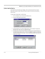
Page 116: ...ce do the following 1 From the Analyze menu choose Select Another Device 2 The Enter IP Address dialog box appears 3 Verify the information in the Enter IP Address dialog box and click Scan This opens...

Page 117: ...Analysis Polling Interval dialog box appears 2 Use your mouse and move the interval to the rate of your specification Then click OK Wireless Link Test Run the wireless link test to verify that your e...

Page 118: ...outer that you want to initialize 3 Click OK to confirm that the IP address is correct 4 Click OK again You should receive the following message Configuraton has been read from the Bridge ip xxx xxx x...

Page 119: ...uter or clients that you want to test Description of Wireless Link Test Window Name Name of the initiator station of the wireless link test Description Initiator station brouter type and firmware vers...

Page 120: ...nicating with the initiator station Address MAC address of the interface of the remote partner Interface The interface of the initiator station that the remote partner is communicating to Radio Type T...

Page 121: ...ets This displays the percentage of test packets successfully received at each end A higher per centage is better If you are loosing a large percentage of packets try realigning the antenna or changin...

Page 122: ...work operation To run the antenna alignment test do the following 1 From the Analyze menu choose Antenna Alignment The Antenna Alignment dialog box appears 2 Enter the following information Interface...

Page 123: ...Glossary for Standard Data Communications...

Page 124: ...al into a tight beam Parabolic or dish grid and Yagi are dif ferent varieties of antennas Antenna Gain The ratio of the power radiated by an antenna in a specific direction versus the power required t...

Page 125: ...ents If the segments are the same the packet is dropped or filtered If the seg ments are different then the packet is forwarded to the correct segment Additionally bridges do not forward bad or misali...

Page 126: ...ed by a conductive shield made of metal foil or wire braid Often used to connect the RF unit and modem unit of a wireless system Code Division Multiple Access CDMA A system in which all users occupy t...

Page 127: ...t Sequence DS A type of spreading technique that multiplies a higher rate PN code to the signal in order to spread the energy of the nar row band signal over a much wider bandwidth for transmission Di...

Page 128: ...through and stores and forwards as well This technique takes more time to examine the entire packet but it allows the switch to catch certain packet errors and keep them from propagating through the...

Page 129: ...frequency between several pre assigned values hopping Although the signal itself looks like a narrow band signal at any given point in time it acts like a spread signal because of the frequency hoppi...

Page 130: ...of communication goes down the secondary method instantly takes over Hub This device on a network collects receives and repeats data to its forwarded destination on the network A hub is also known as...

Page 131: ...rovide personal educational political and economic resources to every cornet of the planet IP Address This address tells the network how to locate the computers or network equipment connected to it IP...

Page 132: ...whereby the antennas of a given link have a sufficient path for communication It requires that at least 60 of the Fresnel zone between them be unobstructed Do not confuse with Loss of Signal Liquid C...

Page 133: ...agement Information Base MIB A database of network parameters used by SNMP and CMIP to monitor and change network device settings It provides a logical naming of all information resources on the netwo...

Page 134: ...the quality of a transmitted signal Obstruction Any man made or natural object that blocks diffracts or reflects a transmitted signal Octet There are four octets in an IP address Each octet contains 8...

Page 135: ...lls lakes etc along a transmission path to determine if a given path is viable for the communication link This is usually done with a computer Personal Communication Services PCS A lower powered highe...

Page 136: ...independence which means that devices that are compatible at the physical and data link layers allowing the user to run many different protocols over the same medium Pseudo random Noise code PN code A...

Page 137: ...RF Unit from the antenna Right arrow This is the right arrow key on your keyboard Router This device filters out network traffic by specific protocol rather than by packet address This device operates...

Page 138: ...e noise floor The same code is known to the receiver and is used to decode the signal Keeping the code secret provides communications security Submask This term allows you to mask section s depending...

Page 139: ...r sensitivity System gain is an important measure of a system s ability to overcome attenuation and perform to a satisfactory level These are measured in decibels per meter dBm Tx Transceiver This is...

Page 140: ..._________________________________________________ ________________________________________________________ ________________________________________________________ ____________________________________...

Page 141: ...Appendix Protocols Ethernet Addresses...

Page 142: ...se response not registered 3C07 3Com NBP Datagram like XNS IDP not registered 3C08 3Com NBP Datagram broadcast not registered 3C09 3Com NBP Claim NetBIOS name not registered 3C0A 3Com NBP Delete NetBI...

Page 143: ...igan 807D 807F Vitalink Communications 8080 Vitalink TransLAN III Management 8081 8083 Counterpoint Computers 8088 808A Xyplex 809B EtherTalk AppleTalk Phase I over Ethernet 809C 809E Datability 809F...

Page 144: ...chneider Koch in Europe and Syskonnect 00005A Xerox 806 unregistered 00005D RCE 00005E U S Department of Defence IANA 000061 Gateway Communications 000062 Honeywell 000064 Yokogawa Digital Computer Co...

Page 145: ...le Co 002017 Orbotech 00201C Excel Inc 00201E Netquest Corporation 00201F Best Power Technology Inc 002021 Algorithms Software Pvt Ltd 002022 Teknique Inc 002024 Pacific Communications Sciences 002025...

Page 146: ...Race Inc 00206E Xact Inc 002074 Sungwoon Systems 002076 Reudo Corporation 002077 Kardios Systems Corporation 002078 Runtop Inc 00207F Kyoelsangyo Co Ltd 002082 Oneac Corporation 002083 Presticom Inc...

Page 147: ...n Ltd 0020E1 Alamar Electronics 0020E7 B W Nuclear Service Company 0020E8 Datatrek Corporation 0020E9 Dantel 0020EA Efficient Networks Inc 004074 Cable and Wireless Communications Inc 004076 AMP Incor...

Page 148: ...rawberry Tree Inc 0040D2 Pagine Corporation 0040D4 Gage Talker Corp 0040D7 Studio Gen Inc 0040D8 Ocean Office Automation Ltd 0040DC Tritec Electronic GMBH 0040DF Digalog Systems Inc 0040E1 Marner Inte...

Page 149: ...Limited 0080D7 Fantum Engineering Inc 0080D8 Network Peripherals 0080DA Bruel Kjaer 0080DD GMX Inc GIMIX 0080E0 XTP Systems Inc 0080E7 Lynwood Scientific Dev Ltd 0080EA The Fiber Company 0080F0 Kyushu...

Page 150: ...D Fuji Photo Film Co Ltd 00C02E Netwiz 00C02F Okuma Corporation 00C030 Integrated Engineering B V 00C031 Design Research Systems Inc 00C032 I Cubed Limited 00C033 Telebit Communications APS 00C034 Dal...

Page 151: ...ogies Inc 00C08D Tronix Product Development 00C08E Network Information Technology 00C08F Matsushita Electric Works Ltd 00C090 Praim S R L 00C091 Jabil Circuit Inc 00C092 Mennen Medical Inc 00C093 Alta...

Page 152: ...ion Engineering Inc 00C0F3 Network Communications Corp 00C0F4 Interlink System Co Ltd 00C0F5 Metacomp Inc 00C0F6 Celan Technology Inc 00C0F7 Engage Communication Inc 00C0F8 About Computing Inc 00C0F9...

Page 153: ...stems Inc 080046 Sony 080047 Sequent 080048 Eurotherm Gauging Systems 080049 Univation 08004C Encore 08004E BICC 080051 Experdata 080056 Stanford University 080057 Evans Sutherland 080058 DECsystem 20...

Page 154: ...00 1E 00 00 00 8019 Apollo DOMAIN 09 00 26 01 00 01 8038 Vitalink TransLAN bridge management 09 00 2B 00 00 00 6009 DEC MUMPS 09 00 2B 00 00 01 8039 DEC DSM DTP 09 00 2B 00 00 02 803B DEC VAXELN 09 0...

Page 155: ...00 00 00 01 802 Active Monitor C0 00 00 00 00 02 802 Ring Parameter Monitor C0 00 00 00 00 04 802 Network Server Heartbeat C0 00 00 00 00 08 802 Ring Error Monitor C0 00 00 00 00 10 802 Configuration...

Page 156: ...___________ ________________________________________________________ ________________________________________________________ ________________________________________________________ _________________...

Page 157: ...Saved Configuration File 4 3 Configuring a SPEEDLAN 4200 4 2 Configuring SPEEDLAN 4100 4200 4 1 Connect the Wireless SPEEDLAN Brouter to Customer s Ethernet LAN 2 7 Connect the Wireless SPEEDLAN Brou...

Page 158: ...iagram 2 8 Installation Steps Installing wireless equipment 2 3 Interface Advanced Interface Setup 5 4 Interface Monitor 11 5 Interface Setup 5 4 Internet Address Classes 7 3 Introduction 1 1 IP ARP T...

Page 159: ...us 4 5 Quick Start 2 1 R Remote Statistics 11 2 Rooftop and Tower Installations Warning 2 2 Running and Securing All Cable 4 5 S Security Button 11 Mb RF Security Setup 5 11 Select Another Device 13 2...

Page 160: ...us PRC Non Polling 5 8 Campus PRC Polling 5 8 Campus PRC Remote Station 5 8 Tunnel Partners Button 6 8 U UDP 11 22 Updating the Firmware 3 4 V Verifying Line of Sight 2 3 W Weatherproofing Connectors...

Page 161: ...Wave Wireless THE CUSTOMER OR RESELLER MAY NOT USE COPY SUBLICENSE ASSIGN OR TRANSFER THE LICENSED MATERIALS OR ANY COPIES THEREOF IN WHOLE OR IN PART EXCEPT AS EXPRESSLY PROVIDED IN THIS LICENSE AGRE...

Page 162: ...t list price If all three years are purchased simultaneously the cost will be 10 per year or 30 of list Years 2 3 can be purchased during the initial year of coverage if the equipment was under extend...

Page 163: ...anty shall not apply if Wave Wireless prebuilt U S FCC approved antenna assemblies have been altered and installed by any persons other than professional wireless installers THE FOREGOING WARRANTIES A...

Page 164: ...Wave Wireless THE CUSTOMER OR RESELLER MAY NOT USE COPY SUBLICENSE ASSIGN OR TRANSFER THE LICENSED MATERIALS OR ANY COPIES THEREOF IN WHOLE OR IN PART EXCEPT AS EXPRESSLY PROVIDED IN THIS LICENSE AGRE...

Page 165: ...nt list price If all three years are purchased simultaneously the cost will be 10 per year or 30 of list Years 2 3 can be purchased during the initial year of coverage if the equipment was under exten...

Page 166: ...anty shall not apply if Wave Wireless prebuilt U S FCC approved antenna assemblies have been altered and installed by any persons other than professional wireless installers THE FOREGOING WARRANTIES A...

Page 167: ...s equipment must be professionally installed In order to comply with FCC RF Exposure requirements this device must be installed in such that a minimum separation distance of 2 meters is always maintai...

Reviews: