E
RROR
! R
EFERENCE SOURCE NOT
FOUND
.
P5186 U
SER
M
ANUAL
V 1.0
Error! Reference source not found.
5.4 RS232 function
5.4.1 Introduction
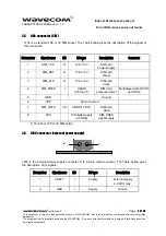
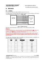
The Starter Kit is fitted with a MAX3238 RS232 transceiver device (U1).
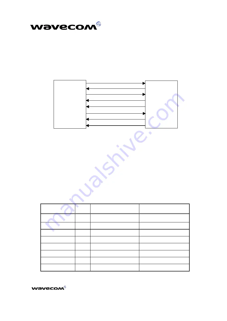
The Starter Kit acts as a DCE (Data Communication Equipment) and is connected to a DTE (Data
Terminal Equipment - PC or terminal) with a “
straight
cable”.
D T E
St art er
Kit
(D CE)
CT 1 0 3 / T X
CT 1 0 8 - 2 / D T R
CT 1 0 5 / RT S
CT 1 0 4 / RX
CT 1 0 6 / CT S
CT 1 0 7 / D SR
CT 1 0 9 / D CD
CT 1 2 5 / RI
Figure 1: RS232 serial link
RS232 link default configuration is made of 6 wires: TX, RX, CTS, RTS, DTR and DSR.
Warning:
When RI and DCD signals are used by the application, the resistors R606 and R607 (0
Ω
resistors) must
be placed on the mother board. In the mother board default configuration, these resistors are not
placed. So, a set of 0
Ω
resistors is provided with the starter kit.
When the SPI2 bus of the WISMO P5186 module is used, resistors R603 and R610 must be unsoldered
and removed from the motherboard, because the SPI2 bus signals (SPI2_DATA and SPI2_CLK) are
multiplexed with DSR1 and DTR1. In that case, the RS232 serial link will be make up of 4 wires only: TX,
RX, CTS and RTS.
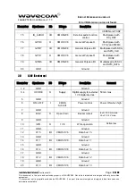
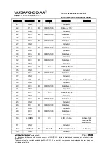
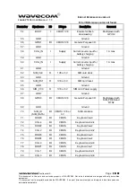
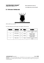
The signal name relashionship between the WISMO Pac P5186 serial interface (V24/CMOS) and
the RS232 interface (V24/V28) is given hereafter:
Pin #
I/O
RS2332 signal
P5186 signal
1
O
DCD
GPIO7
2 O RXD
TXD1
3 I
TXD
RXD1
4 I DTR
DSR1
6 O DSR
DTR1
7 I
RTS
CTS
8 O
CTS
RTS
9 O
RI
GPIO6
confidential ©
Page :
34 / 42
This document is the sole and exclusive property of WAVECOM. Not to be distributed or divulged without prior written
agreement.
Ce document est la propriété exclusive de WAVECOM. Il ne peut être communiqué ou divulgué à des tiers sans son
autorisation préalable.

