WM_PRJ_Q2400_PTS_005 -007
18th January 2006
Confidential©
All rights reserved
Page:
13
/
51
This document is the sole and exclusive property of WAVECOM. Not to be
distributed or divulged without prior written agreement.
0
5
10
15
20
25
30
35
40
45
50
200
400
600
800
1000
1200
1400
1600
1800
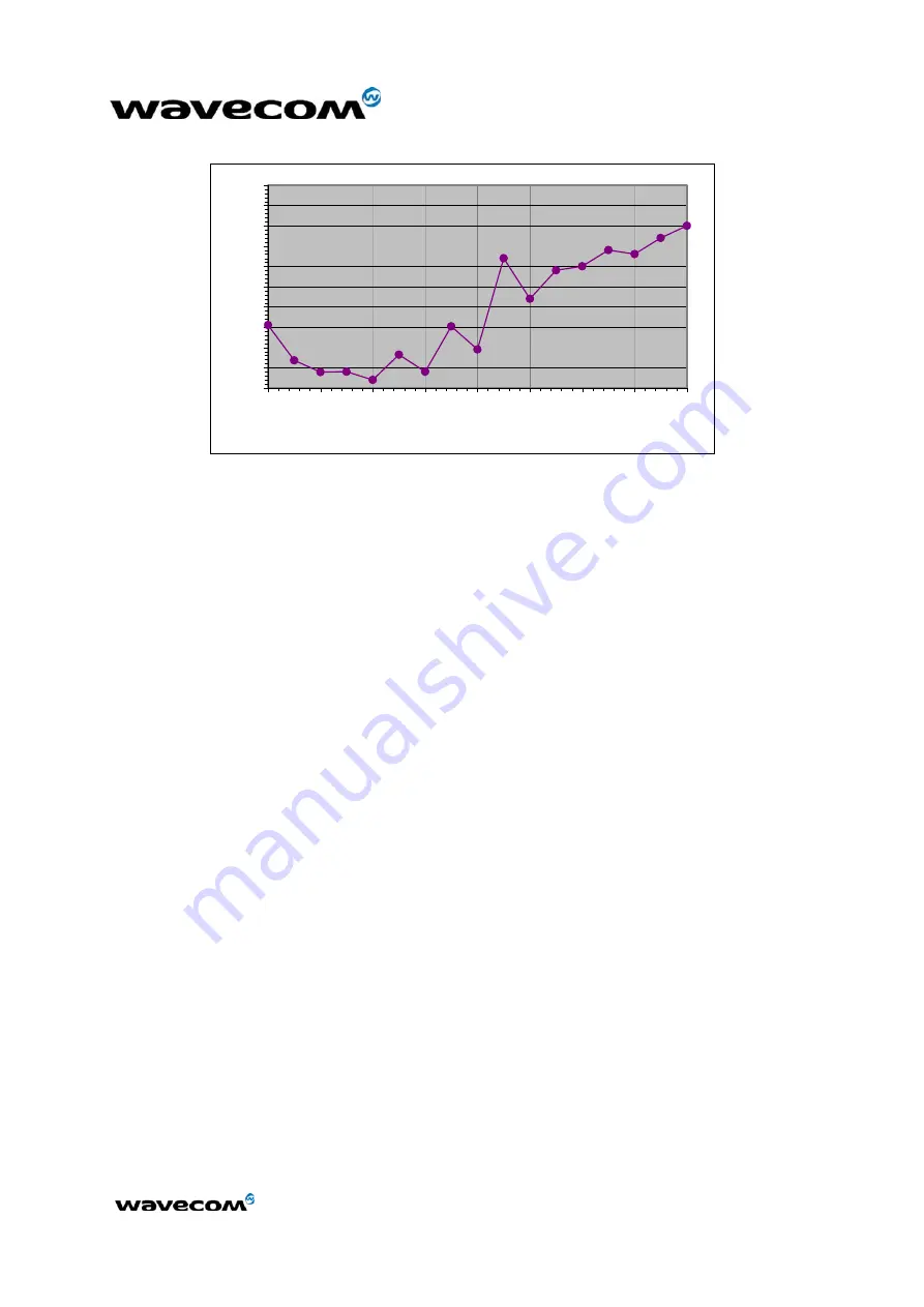
Input Frequency (kHz)
Uripp (mVpp)
for f<100kHz U
ripp
Max = 50mVpp
for f> 1800kHz U
ripp
Max = 40 mVpp
Figure 2: Maximal voltage ripple (Uripp) vs Frequency in GSM & DCS
2.1.2 Design Requirements
2.1.2.1 Risk
VBATT supplies directly the RF components with 3.6 V. It is essential to keep a
minimum voltage ripple at this connection in order to avoid any phase error.
Insufficient power supply voltage could dramatically affect some RF
performances:
•
TX power of course and modulation spectrum,
•
EMC performances (spurious emission),
•
Emissions spectrum,
•
Phase error and frequency error.
2.1.2.2 General design rules
A careful attention should be paid to:
•
Quality of the power supply: capacity to deliver high peak current in a
short time (bursted radio emission), low ripple and low impedance.
•
The battery charger line must support 800 mA to comply with the voltage
level required for the product.
•
The VBATT lines on the PCB must support peak currents with a voltage
drop below the specified limit.
In order to test the supply tracks, a burst simulation circuit is shown hereafter.
This circuit simulates burst emissions, equivalent to bursts generated when
transmitting at full power.


