WM_PRJ_Q2400_PTS_005 -007
18th January 2006
Confidential©
All rights reserved
Page:
41
/
51
This document is the sole and exclusive property of WAVECOM. Not to be
distributed or divulged without prior written agreement.
4 Mechanical specifications
Attention should be paid to:
•
Antenna cable integration (bending, length, position, etc),
•
Legs of the module to be soldered on the Ground plane (
see Wavecom
recommendation for lead free soldering in Section 5.3).
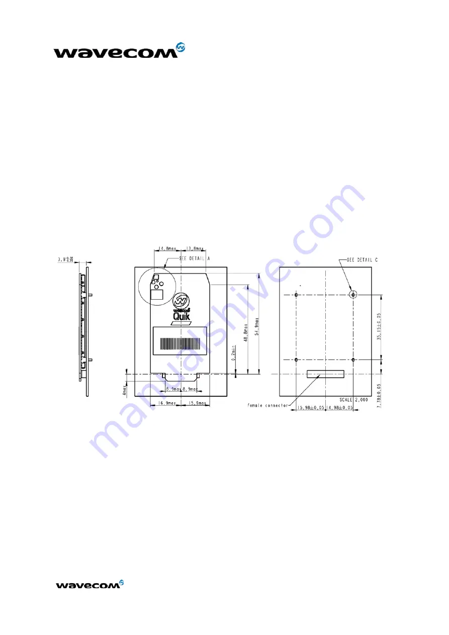
Figure 28 gives the overall dimension of the module, taking into account the PCB
dimension and placement tolerances.
It is important to assure that no component or mechanical element will enter in
contact with the module even in case of vibration or manipulation of the final
product.
These contacts may produce bad electrical connection on the 60-pin general
purpose connector.
Figure 28: Maximum bulk occupied on the application board

