B
A
A
B
16
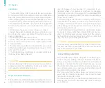
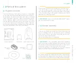
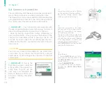
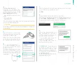
Inserting a sensor and s
tarting a session
/
English
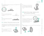
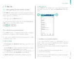
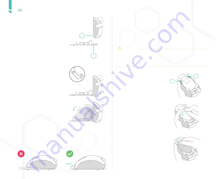
3.
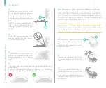
Grip the left tab and peel it back to
remove the second section of the
liner.
Make sure the adhesive does not
fold onto itself before or during
application.
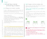
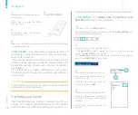
3.
Hold the sensor insertion tool, with
the tab (B) pointing down, perpen-
dicular to the sensor assembly.
Align the tab directly above the
opening (A) on the sensor assem-
bly.
NOTE: The sensor assembly ope-
ning (A) is for alignment and po-
sitioning of sensor insertion tool
tab (B).
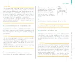
4.
Lower the sensor insertion tool,
steering the tab into the opening
on the sensor assembly.
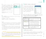
5.
Tilt the raised end of the sensor in-
sertion tool downward to meet the
sensor assembly, until you hear a
click.
6.
The sensor insertion tool and sensor guide should snap together
without a gap.
Check for a gap between the sensor insertion tool and sensor
guide. If there is a gap, see
SECTION 15.7
.
4.9
Remove the sensor adhesive liner
Once you have cleaned the insertion site, you are rea-
dy to remove the liner on the sensor adhesive patch. To
complete this step, you need the sensor insertion tool
with the sensor assembly attached.
CAUTION
The adhesive is sterile; do not touch the centre of the
adhesive material. Only touch the perimeter of the adhe-
sive when removing the liner.
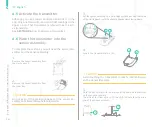
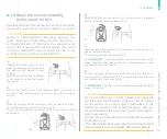
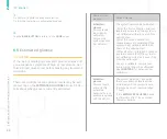
1.
Hold the sensor insertion tool with
the sensor adhesive liner facing
up.
Locate the tabs (A and B) on each
side of the liner.
2.
Grip the right tab and peel it back
to remove the first section of the
liner.
Summary of Contents for A.MENARINI diagnostics GlucoMen Day CGM
Page 1: ...User Guide...
Page 65: ......

