www.teamWavelength.com
© 2005-2019
WTC3293-14001 BOARD WITH DISPLA
Y
PAGE 3
WTC3293-14400-J
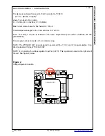
1. SELECT POWER SUPPLY VOLTAGE and INSTALL JUMPER
The WTC3293-14001 has been designed to operate at one of three discrete voltages: 7V, 9V, or 12V.
The POWER jumper must be installed for the chosen voltage.
To choose the appropriate voltage for your application, use Wavelength’s online Safe Operating Area
(SOA) calculator for Temperature Controllers:
www.teamwavelength.com/support/design-tools/soa-tc-calculator/
.
a. On the calculator page, in the
Product
dropdown menu, click
WTC3293-14
.
b. In the
Max. Heatsink/Enclosure Temperature
text box, type the maximum ambient temperature
the controller will experience.
c. In the
Limit Current
text box, type the limit current setting you will use.
d. In the
Load Impedance
text box, type the impedance of the thermoelectric (Vmax / Imax).
e. In the
Supply Voltage
text box, type the power supply voltage you want to use. This number will
be 7, 9, or 12.
f. Click
Find SOA Compliance
. A graph showing the Safe Operating Limit and the Load Line is
generated. If the calculations are not within the Internal Power Dissipation Safe Operating Area,
reduce the power supply voltage until the configuration stays within the SOA.
Install a jumper indicating which power supply you have selected on the header near the DC input
plug. NOTE: When you plug in the supply, make sure the Enable Switch is OFF. Do not operate with
a voltage less than 7 V.
WHY? The WTC3293-14001 uses the WTC3243 temperature controller, which is designed to drive
currents as high as 2.2 Amps. The resistance of the thermoelectric will create a voltage drop across
the thermoelectric proportional to the current (Voltage = Current x Resistance). The voltage drop
across the WTC3243 will equal the power supply voltage minus the thermoelectric voltage. If the
power dissipated by the WTC3243 is too high (Power = Voltage x Current), the WTC3243 will overheat
and be destroyed.
2. SELECT HEAT AND COOL CURRENT LIMITS
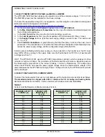
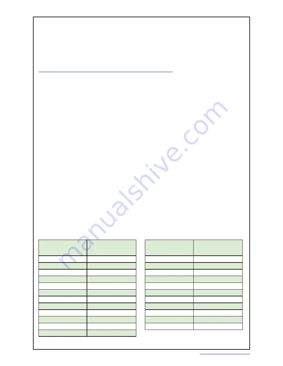
To protect the thermoelectric from over current damage, set the heat and cool current limits as follows.
The standard product is shipped with 2.00 k
Ω
resistors for 0.5 A cooling and heating limits.
Resistors should be 5% metal film. Carbon resistors will introduce noise and instabilities.
OPERATING THE WTC3293-14001
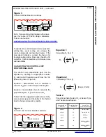
Table 1
Current Limit Set Resistor vs Maximum Output Current
MAXIMUM OUTPUT
CURRENT (A)
CURRENT LIMIT
RESISTOR (k
Ω
)
R
A
or R
B
0.0
1.58
0.1
1.66
0.2
1.74
0.3
1.83
0.4
1.92
0.5
2.01
0.6
2.11
0.7
2.22
0.8
2.33
0.9
2.45
1.0
2.58
1.1
2.71
MAXIMUM OUTPUT
CURRENT (A)
CURRENT LIMIT
RESISTOR (k
Ω
)
R
A
or R
B
1.2
2.86
1.3
3.01
1.4
3.18
1.5
3.36
1.6
3.55
1.7
3.76
1.8
3.98
1.9
4.23
2.0
4.50
2.1
4.79
2.2
5.11

