www.teamWavelength.com
© 2005-2019
WTC3293-14001 BOARD WITH DISPLA
Y
PAGE 4
WTC3293-14400-J
R
=
100,000
100
P
- 1
[Ω]
( )
( )
P
=
100
100,000
R
P
+ 1
[Amps / Volts]
OPERATING THE WTC3293-14001, continued
Table 2
Proportional Gain Resistor R
P
vs Sensor Type
and Thermal Load Speed
Proportional Gain
Resistor, R
P
Proportional Gain,
[Amps/Volt]
Sensor Type/
Thermal Load Speed
4.99 k
Ω
5
Thermistor/Fast
Thermistor/Slow
24.9 k
Ω
20
20
100 k
Ω
50
50
RTD/Fast
RTD/Slow
Open
100
24.9 k
Ω
AD590 or LM335/
AD590 or LM335/
Fast
Slow
100 k
Ω
To optimize the control loop (minimize overshoot,
settling time, avoid cycling, etc.) change the
control parameters as described below. If the
load doesn’t stabilize, contact the factory for
troubleshooting advice. Resistors should be 5%
metal film. Carbon resistors will introduce noise
and instabilities.
3. ADJUSTING THE CONTROL LOOP
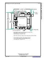
PROPORTIONAL GAIN
The control loop proportional gain can be
adjusted by inserting an appropriate resistor,
R
P
, into Control P location to set P from 1 to 100.
(Shown in green in Figure 4.)
Equation 1 demonstrates how to calculate a
value for R
P
given a desired proportional gain.
Equation 2 demonstrates how to calculate the
proportional gain, P, given a value for R
P
.
Table 2 lists the suggested resistor values for R
P
versus sensor type and the ability of the thermal
load to change temperature rapidly.
Equation 1
Calculating R
P
from P
Equation 2
Calculating P From R
P
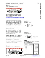
CONTROL
P
I
Figure 4
Control P and Control I Resistor Locations
Figure 3
Current Limit Set Resistor Locations
A
B
Note: If you want a wiring diagram with values,
use the online WTC3243 design calculator.
This can be found at:
www.teamwavelength.com/support/design-tools/wtc-calculator/

