S E C T I O N
O P E R A T I O N
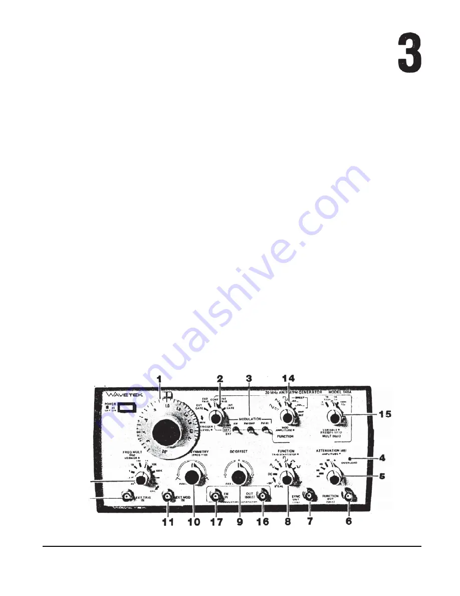
3.1 CONTROLS AND CONNECTORS
b. EXT TRIG
Mode -
Same as for EXT GATE
The following item
numbers are keyed to figure 3-1.
3.1 .1
Main Generator
mode, except the main generator output is
one cycle of selected signal only.
c. CONT Mode -
The output signal is continuous.
1
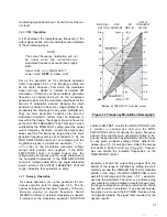
Frequency Dial - The frequency control of the
main generator.
The setting on this dial
multiplied by the FREQ MULT
12
setting is the
basic output frequency of the generator at the
FUNCTION OUT.6 and SYNC OUT 7 BNCs.
The FREQ VERNIER
12
and, in some cases,
the modulation generator also affect the main
generator frequency.
2
Mode Switch - This outer switch selects the
operating mode of the main generator as follows:
a.
EXT GATE Mode -
The main generator is
quiescent until a proper gate signal is applied
at the EXTTRIG IN BNC 13 and then outputs
the selected signal for the duration of the gate
signal, plus the time to complete the last cycle
generated.
12
13
d.
INT TRIG -
Same as for EXTTRIG mode, ex-
cept the trigger signal is applied internally by
the modulation generator.
e. INT GATE -
Same as for
EXT GATE,
except
the gate signal is applied internally by the
modulation generator.
TRIGGER LEVEL
Control -
T h i s inner control
is a continuously variable adjustment of the trig-
ger circuitry firing point. When full ccw, a posi-
tive going pulse at approximately - 7.5V is re-
quired for triggering (see figure
3-2).
In the full
cw position,
a
positive going pulse at approxi-
7.5V or more positive voltage is re-
quired for triggering. In the GATE modes, the‘
generator will run continuously when the control
is cw of 12 o’clock.
MOOULATION GENERATOR
Figure 3-1 Controls and Connectors
3-1


