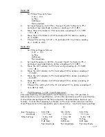
With the abave setti ngs , the 452 Post F i l ter/Amplifier provides 40 dB of goin and
estab l ishes a noise measurement bandwidth of 0 . 1 Hz to 1 00 KHz . (A noise
bandwidth of 1 00 KHz is, for a l l pra cti ca l purposes, equal to the 3 -c1B band
width of a 4th-order fi l ter . )
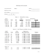
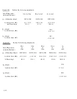
Measure noise with the 3620A RMS Voltmeter for the CUT setti ngs shown i n
Tabl e 4 .4 . Output Broadband Noise a f the C UT is cal cul ated a s fol l ows:
Output Noise
=
1 00
e .
Maximum Stopband Attenuation
x Voltmeter Reading
Connect equi pment os shown in Setup # 3 a nd set the Channel Under Test as fol low s :
1 . 00 x 1 0 K Cutoff Frequency
H i Pass
2 0 d B Gain
F lat Ampl .
Set the 5 1 00 Frequency Synthesizer to 1 00 KHz and increase its output amplitude
unti l CUT output is equal to ful l -scal e signal of 7. 1 V nms ( + 1 7 d BV ) .
Set the 1 4l T S pectrum Ana l yzer contro l s os fol l ows:
I n put Level
Bandwidth
S ca n W idth
S ca n Time
Log Ref Level
-1 0 dBV
300 Hz
2 KHz/div
50 msec
Adjust for ful l -sca l e Display after tuning analyzer
to 1 00 KHz
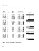
Set the CUT and i nput frequency to the val ues shown in Table 4 . 5 . I n each case ,
tune the S pectrum Anal yzer to the i n put frequency and increase Input Level control
setting to -60 dBV . Read the ampl itude of the signal d isplayed on the scree n .
The Maximum Stopband Attenuation with respect to ful l -scale signa l i s ca l cu lated
as fol l ows:
A
=
(50 dB + D isplay dB)
4-7
Summary of Contents for 452
Page 16: ......


