4 .6
PRI NTED
C IRCUIT BOARD k E PAIR
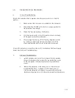
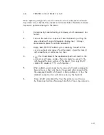
When replacing integrated circuits or other el ectronic components soldered
to printed-circui t boords, the procedures i ndicated below shoul d be fol l owed
to prevent potential damage to the board .
1 .
2 .
3 .
4 .
5 .
6 .
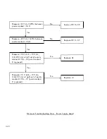
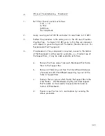
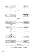
Determine by troubl eshooting techniques, wh ich component has
fai l ed .
Remove the defective component from the baard by cutting the
pins or leads with a sma l l diagonal cl ipping tool . (Always
remove and repl ace the entire componenL)
Apply heat (40-50 W soldering iron) sparingl y to each of the
cut pins or l eads and remove from the board; c l ean the hol e(s)
with a toothpick or solder suction tool .
Form the tinned l eads of the replacement part and insert i n the
printed circuit holes; solder, then trim l eads to extend 1 /1 6-
inch beyond the back surface of the board . (Use only 63-37
solder with maximum 1 /1 6 -inch diameter . )
When soldering semiconductor devices and al l sma l l components,
be sure to use a heat sink tool or l ong-nosed pl ier connected to
the component l ead(s) wh i l e each is being soldered . A l low the
soldered connection to cool before removing the heat sink .
C l ean a l l dirt and solder-flux from the printed circuit traces
by l iberal appl ication of isopropyl a l cohol or freon-type sol vents .
4-25
Summary of Contents for 452
Page 16: ......


