2 of 9
WX-501-0536 • 01.22
Communication Ports
The back of the Click 510 features a 5-position connector that plugs into a T-bus connector and provides power
and RS-485 communication to the device. It also passes RS-485 communication to all other devices on the T-bus.
Usually, the RS-485 T-bus connection port is the primary communication.
The top of the module has two pluggable screw terminal blocks for wiring in communication. The first block has
-485, +485 and two ground screw terminals for wiring RS-485 communication. These RS-485 lines are physically
connected to the RJ-11 jack on the front of the module. The second block has a -232, +232 and two ground screw
terminals for wiring RS-232 communication. In many 510 troubleshooting applications, the terminals on these two
blocks are unused.
The front of the module has an RJ-11 jack for RS-485 communication. This jack is physically connected to the RS-
485 communication lines of the RS-485 pluggable screw terminal block on top of the module.
The front of the module also has a DB-9 port for RS-232 communication. This port performs differently than
similar ports on many other Click modules. While it can be used to convert RS-485 communications to RS-232,
this is not its normal usage. Instead on the Click 510 this port is normally used to upgrade the Click 510 program
or reprogram the unit for custom applications. However, if you are using a modified RS-232 DB-9 serial cable
connector (with the DTR pin removed) it can be used to convert RS-485 communications to RS-232.
Note.
If this pin is not removed or disabled using terminal software like Docklight, the Click 500 will enter Program
mode when a connection is made using Windows HyperTerminal. In Program mode all of the faceplate LEDs will
turn off. To exit Program mode, power cycle the device.
While the device, as a Click 500 series module, has two digital/output ports, the standard Click 510 application
does not use these.
Any data on one port will be transmitted simultaneously on all other ports.
Configuration Features
The following are features of the Click 510 used for configuration.
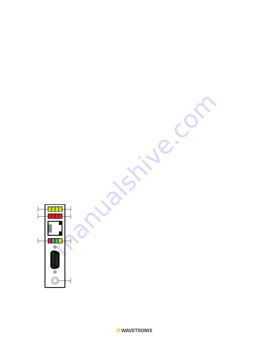
Sub Menu 1
Sub Menu 2
Main Menu
Push-button
Yellow LEDs
Red LEDs
Multicolored LEDs
The yellow and red banks of LEDs display submenu selections and application information. See the Operating
Modes section of this document for more information.
The system LEDs (multicolored bank in the middle of the module) have dual functions: they are activity indicators,


