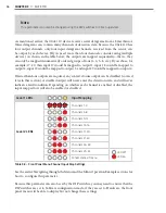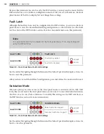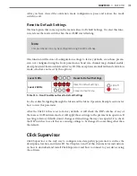
104
CHAPTER 9
•
CLICK 110
The System >
Settings
tab lets you configure and view many of the parameters that are also
available elsewhere on the device (see Table 9.1 earlier in this chapter for more informa-
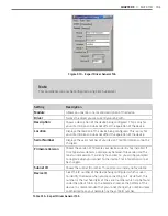
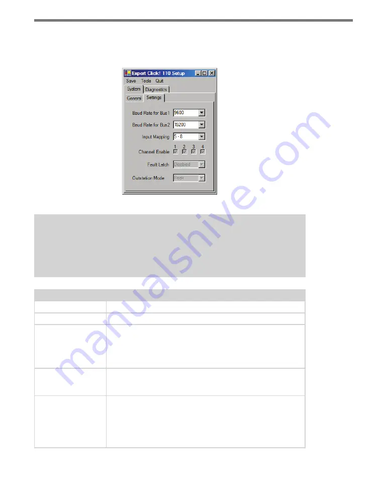
tion). The tab has the following parameters (see Figure 9.11 and Table 9.16):
Figure 9.11 – Expert Driver Settings Tab
Note
These parameters can also be configured using the DIP switches or the front panel
menu; if in the DIP switches they are set to Hardware mode, the parameters will ap-
pear grayed out on this screen.
Setting
Description
Baud Rate for Bus 1
Lets you change the baud rate, in bps, of bus 1.
Baud Rate for Bus 2
Lets you change the baud rate, in bps, of bus 2.
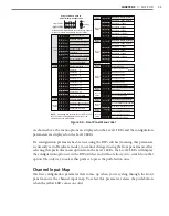
Input Mapping
Lets you assign input datagram channels received from the sensor to
the device’s four output channels. The outputs are mapped sequen-
tially—that is, they can only be mapped in numerically ordered groups
of four (1–4, 5–8, etc.). See Input Mapping in either the DIP Switches
or Front Panel Menu sections in this chapter for more information.
Channel Enable
Lets you choose which of the output channels are enabled. Any com-
bination of outputs can be enabled. A disabled output will never enter
the detection state, and will never indicate a fault condition.
Fault Latch
Lets you view if Fault Latch is enabled. See Fault Latch in the DIP
Switches section of this chapter for more information.
Fault latching can only be configured using the DIP switches, so this
parameter will always be grayed out, allowing you to view but not
change the configuration of this parameter.
Summary of Contents for Click 100
Page 1: ...Click 100 400 Series USER GUIDE...
Page 11: ......
Page 17: ......
Page 27: ......
Page 41: ......
Page 43: ......
Page 79: ......
Page 129: ......
Page 145: ......
Page 161: ......
Page 175: ......
Page 183: ......
Page 187: ......
Page 207: ......
Page 219: ......
Page 225: ......
Page 245: ......
Page 259: ......
Page 260: ...www wavetronix com...

