108
CHAPTER 10
•
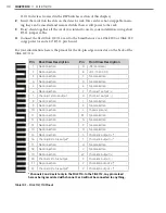
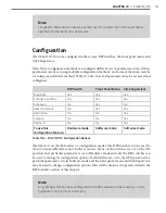
CLICK 112/114
Physical Features
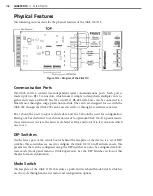
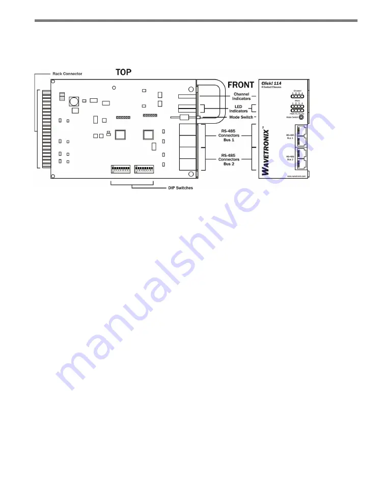
The following sections describe the physical features of the Click 112/114.
Figure 10.2 – Diagram of the Click 114
Communication Ports
The Click 112/114 contain two independent serial communications ports. Each port is
made up of two RJ-11 connectors, which make it simple to daisy-chain multiple cards to-
gether and create an RS-485 bus. The two RJ-11 RS-485 data buses can be connected to a
SmartSensor through a surge protection module (the cards are designed for use with the
Click 222, though the Click 200 can be used as well), or through a serial data converter.
Bus 1 should be used to report vehicle data, and bus 2 should be used for configuration.
Having one bus dedicated to each function leads to optimum Click 112/114 performance.
On certain newer devices, the buses are labeled as Data and Control to let you know which
one to use.
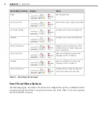
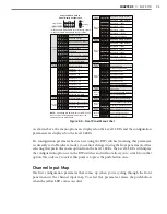
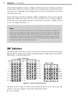
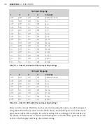
DIP Switches
On the lower part of the circuit board, behind the faceplate of the device, is a set of DIP
switches. These switches are used to configure the Click 112/114 in Hardware mode. The
parameters that can be configured using the DIP switches can also be configured via Soft-
ware mode (front panel menu or Click Supervisor). See the DIP Switches section of this
chapter for more information.
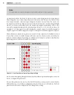
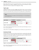
Mode Switch
The faceplate of the Click 112/114 features a push-button labeled Mode Switch, which is
used to cycle through and select menu and configuration options.
Summary of Contents for Click 100
Page 1: ...Click 100 400 Series USER GUIDE...
Page 11: ......
Page 17: ......
Page 27: ......
Page 41: ......
Page 43: ......
Page 79: ......
Page 129: ......
Page 145: ......
Page 161: ......
Page 175: ......
Page 183: ......
Page 187: ......
Page 207: ......
Page 219: ......
Page 225: ......
Page 245: ......
Page 259: ......
Page 260: ...www wavetronix com...

