CHAPTER 15
• CLICK 203
157
Note
The battery fuse must be removed when installing or replacing the module.
Installation
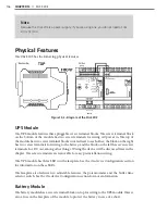
Use the following tables to wire the UPS and battery.
Wiring into the UPS Module
Terminal
Connection
L (+)
AC line (black) in
N (–)
AC neutral (white) in
Table 15.1 – Wiring into the UPS Module
Note
Ensure power to AC mains is disconnected while wiring the AC input.
Wiring out of the UPS Module
Terminal
Connection
+
+DC out (red)
–
-DC out (black)
Alarm
Active switching output (see Signaling Outputs section)
Bat.-Mode
Active switching output (see Signaling Outputs section)
Bat.-Charge
Active switching output (see Signaling Outputs section)
R1
Remote terminal (see Remote Shutdown section)
R2
Remote terminal (see Remote Shutdown section)
Table 15.2 – Wiring out of the UPS Module, 7-terminal Block
Terminal
Connection
B
+DC to battery (red)
Battery –
-DC to battery (black)
Table 15.3 – Wiring Out of the UPS Module, 2-terminal Block
Summary of Contents for Click 100
Page 1: ...Click 100 400 Series USER GUIDE...
Page 11: ......
Page 17: ......
Page 27: ......
Page 41: ......
Page 43: ......
Page 79: ......
Page 129: ......
Page 145: ......
Page 161: ......
Page 175: ......
Page 183: ......
Page 187: ......
Page 207: ......
Page 219: ......
Page 225: ......
Page 245: ......
Page 259: ......
Page 260: ...www wavetronix com...

