44
CHAPTER 6
•
CLICK 100
Physical Features
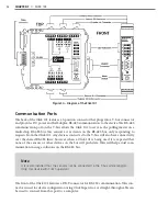
The Click 100 has eight primary and eight secondary contact outputs, which all share a logic
ground (see Figure 6.2).
Figure 6.2 – Diagram of Click 100
Communication Port
The back of the Click 100 features a 5-position connector that plugs into a T-bus connector
and provides power and RS-485 communication to the device. It also passes RS-485 com-
munication from the Click 100 to all other devices on the T-bus when pressing the Mode
button during configuration (see the On-device Configuration section of this chapter for
more information).
Screw Terminals
The contact closure outputs are wired to a controller, data logger or BIU (Bus Interface
Unit) using the pluggable screw terminals on the top and bottom of the Click 100. The top
screw terminals are labeled 1–8 and represent the primary outputs. Primary 1 (P1) repre-
sents the lane closest to a side-fire SmartSensor and the remaining outputs represent the
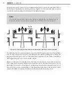
lanes as they sequentially get further from the sensor. For dual-loop emulation, the contact
closure outputs must be wired with the primary always leading the secondary (see Figure
6.3).
Summary of Contents for Click 100
Page 1: ...Click 100 400 Series USER GUIDE...
Page 11: ......
Page 17: ......
Page 27: ......
Page 41: ......
Page 43: ......
Page 79: ......
Page 129: ......
Page 145: ......
Page 161: ......
Page 175: ......
Page 183: ......
Page 187: ......
Page 207: ......
Page 219: ......
Page 225: ......
Page 245: ......
Page 259: ......
Page 260: ...www wavetronix com...

