WX-500-0317
© 2020 Wavetronix LLC. All rights reserved. Protected in the US by patents viewable at www.wavetronix.com/en/legal. Protected by Canadian Patent Nos. 2461411; 2434756; 2512689; and European Patent Nos. 1435036;
1438702; 1611458. Other US and international patents pending. Wavetronix, SmartSensor, Click, Command and all associated logos are trademarks of Wavetronix LLC. All other product or brand names as they appear are
trademarks or registered trademarks of their respective holders. Product specifications are subject to change without notice. This material is provided for informational purposes only; Wavetronix assumes no liability
related to its use.
1
Tear the tab off the silicon dielectric compound that came with the sensor.
2
Squeeze half of the compound on the connector at the base of the sensor.
3
Insert the cable connector into the sensor connector (be aware that it’s keyed).
4
Twist the cable connector clockwise until you hear it click into place.
5
Run the cable through the pole. Leave a small amount of slack at the top;
this reduces strain, allows you to create a drip loop, and gives you some-
thing to work with should you need to move the sensor’s spot on the pole in the future.
6
If you’re using a junction box, terminate the cable in it, then run a homerun cable from there to the
cabinet. If you’re not using a junction box, run the sensor cable to the cabinet. In either case, do
not strip the insulation on the conductors when terminating the cable.
1
Put the Click 65x on a shelf or mount it to the side of the cabinet; connect the sensor cable(s) to the terminal block plug(s).
2
Make sure each switch by the sensor port is turned on and the LED is illuminated.
3
If your cabinet is SDLC compatible, connect a cable from the SDLC bus on the Click 65x to the controller. If your cabinet isn’t
SDLC compatible, connect from the sensor port RJ-11 jacks to contact closure cards to communicate with the controller.
7
Configure the Click 65x
8
Check sensor operation in the SmartSensor Manager Advance software
5
Attach the cable
6
Install cabinet equipment
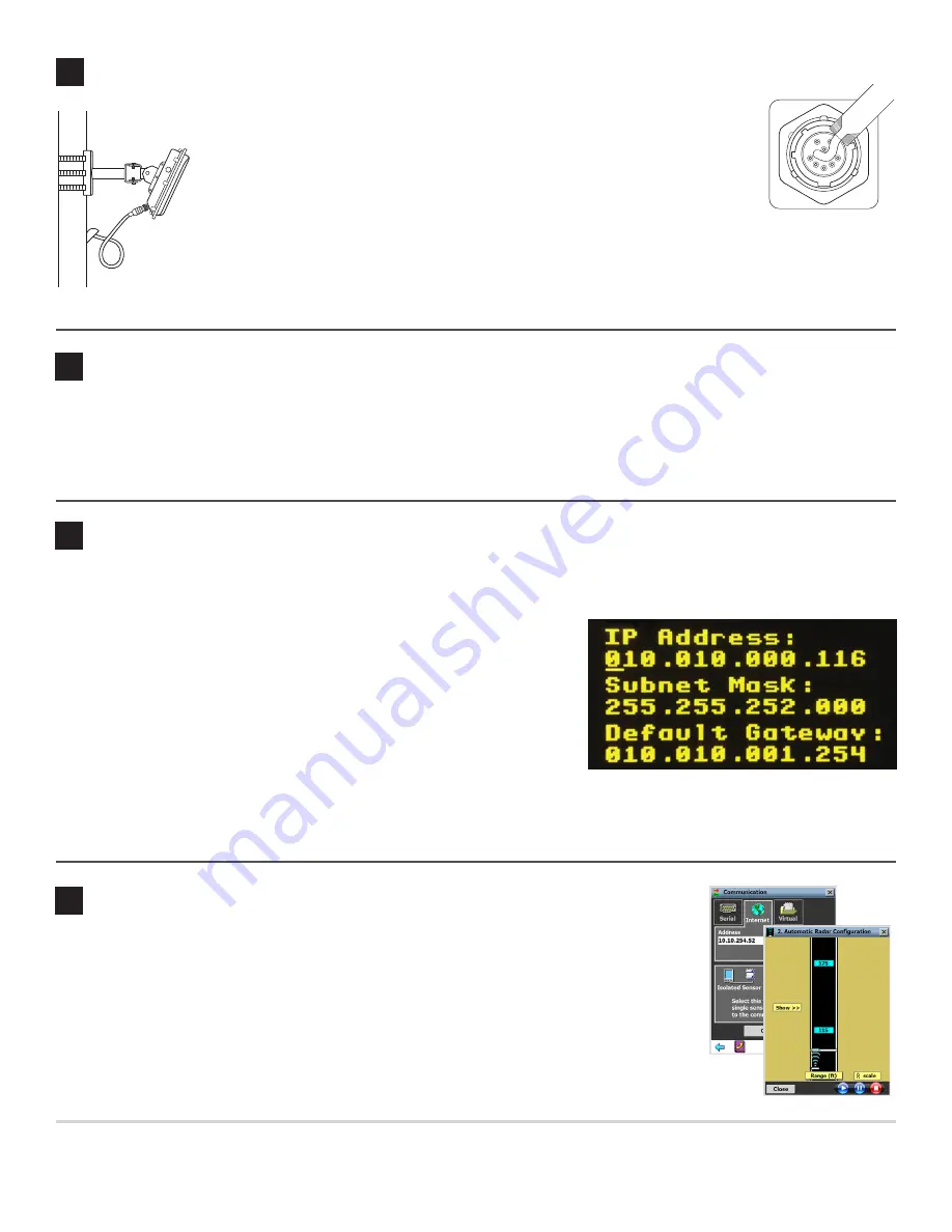
The Click 65x is designed to be communicated with over Ethernet. Before you can connect it to your network, you need to
set the static IP address, subnet mask and default gateway (these numbers should be determined by your IT personnel).
1
Use the arrow keys and screen on the faceplate to access the OLED menu.
2
On the main screen, navigate down to Network Setup and press the
Accept
(green check mark) button to open the networking screen (shown at right).
3
Set your desired IP address by following these steps: use the left and
right arrow keys to highlight a number, then use the up and down arrow
keys to change that number. Then move to the next number. Repeat until
all the numbers are changed.
4
Press the right key again to navigate down to the subnet mask line.
5
Repeat steps 2 and 3 for the subnet mask and default gateway.
6
When you’re done with all three, push the check mark button to confirm your changes.
After you’re done, connect an Ethernet cable to the RJ-45 jack on the faceplate to connect your Click 65x to your network.
1
Click
Communication
on the main screen and then click
Internet
at the top of the screen.
2
Under
Address
and
Port
, enter the IP address and port number of the Click 65x.
3
Click
Multi drop Network
and enter the sensor ID of the sensor you want to talk to.
4
On the main menu, click
Sensor Configuration
, then
2. Automatic Radar Configuration
.
The screen that opens shows vehicle detections as moving blue bars, called trackers. If the
trackers match traffic on the road, the sensor is working properly.
Note.
For configuration instructions, see the
SmartSensor Advance User Guide
.


