WaveWare Rauland responder 5000, User Manual
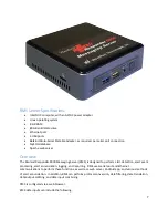
The WaveWare Rauland Responder 5000 is a cutting-edge communication system for healthcare facilities. With our user manual, you can easily navigate the features and functions of this device. Download the free manual from 88.208.23.73:8080 to maximize the potential of your Responder 5000.
Share
Download


Reviews:
No comments
Related manuals for Rauland responder 5000

Univerge SV8100
Brand: NEC Pages: 2

ShareCenter DNS-343
Brand: D-Link Pages: 12

VCS
Brand: TANDBERG Pages: 187

BladeCenter QS20
Brand: IBM Pages: 92

BladeCenter JS20
Brand: IBM Pages: 218

HS21 - BladeCenter - 8853
Brand: IBM Pages: 80

8835 - Eserver 325 - 1 GB RAM
Brand: IBM Pages: 62

8835 - Eserver 325 - 1 GB RAM
Brand: IBM Pages: 2

8676 - Eserver xSeries 335
Brand: IBM Pages: 92

8670 - Eserver xSeries 345
Brand: IBM Pages: 60

8647 - Eserver xSeries 225
Brand: IBM Pages: 182

8480 - Eserver xSeries 205
Brand: IBM Pages: 64

79463AU
Brand: IBM Pages: 2

71455RU
Brand: IBM Pages: 136

RS/6000 SP
Brand: IBM Pages: 480

450 xSeries
Brand: IBM Pages: 68

@Server pSeries 630 6C4
Brand: IBM Pages: 180

eServer 380 xSeries
Brand: IBM Pages: 54


