34
LED Display
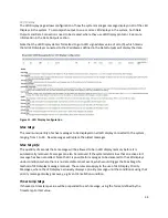
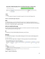
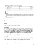
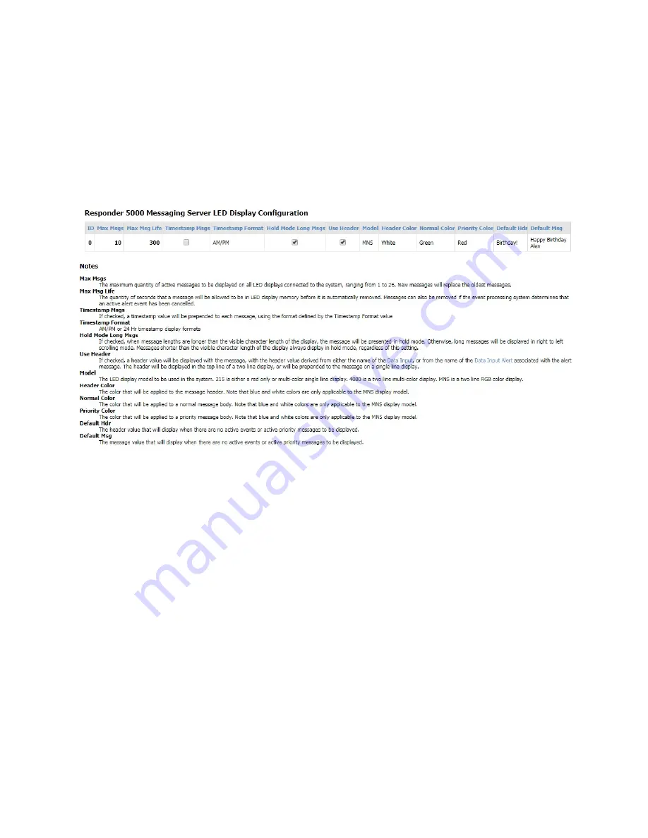
The LED Display page allows configuration of how the system manages message display on all of the LED
Displays in the system. To accomplish output to one or more LED displays in the system, both Data
Outputs and Data Connections need to be created, where they use LED Display protocol. See more
information in the Data Outputs section.
Note that the LED Display data is formatted to go to LED sign address value of zero (0), which means
that all LED displays connected to the IP addresses defined in the Data Outputs will display the data.
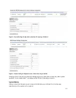
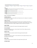
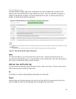
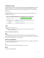
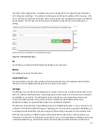
Figure 11 - LED Display Configuration
Max Msgs
The maximum quantity of active messages to be displayed on all LED display connected to the system,
ranging from 1 to 26. New messages will replace the oldest messages.
Max Msg Life
The quantity of seconds that a message will be allowed to be in LED display memory before it is
automatically removed. Messages can also be removed if the system determines that an active alert
message has been cancelled. Note that it is possible for messages to be delivered to the LED displays
under conditions where there is no detectable cancel event, which would trigger the Max Msg Life
method of LED display message removal. These rules also apply to the use of LED Display Priority
Messages, where the LED display exclusively displays a priority message until the condition causing that
priority message display goes away, e.g Event Cancellation condition.
Timestamp Msgs
If checked, a timestamp value will be prepended to each message, using the format defined by the
Timestamp Format value.

