Wavin Tempower Control Manual
Wavin Tempower Control
Heating and Cooling systems
.
Wavin Tempower Control Manual
Wavin Tempower Control
Heating and Cooling systems
.
27
7
7..2
2 P
Prro
og
grra
am
m 2
2
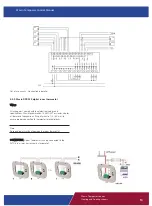
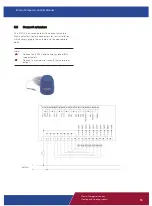
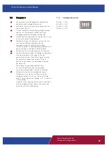
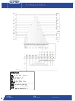
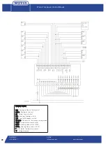
Six rooms can be separately temperature
controlled with Analogue thermostat.
Temperature and relative humidity remote sensor
with voltage output must be connected to the
dew point inputs of the first two control circuits.
Temperature: 0-50
°
C (0-10V), Relative
Humidity: 0-100 RH% (0-10V).
Dew point sensor may be also used on control
circuits 3 to 5.
Output 8 indicates the heating/cooling demand
and the last two outputs control fault-free
changeover between cooling and heating.
Output 7 indicate the drying demand.
Output terminal strip points of control circuits out
of use must be left unconnected.
Thermostat inputs of control circuits out of use
must be connected in parallel with the change
over input of cooling and heating. Otherwise
output 8 (heating/cooling demand) will be
continuously switched in cooling mode.
Control circuit 6 may be used only for heating.
Comfort/Economy mode :the energy saving mode
may be adjusted on C\E input or via the
communication channel. Then the set point is
given by thermostat connected to input "THEco",
and the six rooms are controlled in parallel based
on this. The energy saving mode operates only in
case of heating, energy saving mode set in the
cooling mode switches off cooling.
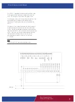
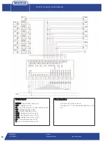
Mixing Valve Control: controlled inlet water
temperature may be set with the use of the
analogous output (010V) as well as of "Temp"
input. The set point of control in case of cooling
is 15
°
C, and 45
°
C in case of heating.
If the value of dew point temperature calculated
from the signals of the remote sensor and
increased by 2.2
°
C exceeds 15
°
C, then this
value will be the set point of the downstream
water temperature control in case of cooling, and
thereby the temperature of the controlled cold
water will be always by 2.2
°
C higher than the
dew point temperature.
If no control is required, the terminal strip points
of the analogous output and of the measuring
input must be left unconnected
7.2.1.
Configuration switch
Switch 1 = OFF
Switch 2 = ON
Switch 3 = ON
Switch 4 = ON
Design Manual
Heating and Cooling systems
Design Manual
Heating and Cooling systems
Design Manual
Heating and Cooling systems
Design Manual
Heating and Cooling systems
Design Manual
Heating and Cooling systems
Design Manual
Heating and Cooling systems
Design Manual
Heating and Cooling systems
Design Manual
Heating and Cooling systems
Design Manual
Heating and Cooling systems
Design Manual
Heating and Cooling systems
Design Manual
Heating and Cooling systems

