background image

Wavin Tempower Control Manual

Wavin Tempower Control 

Heating and Cooling systems


.

Wavin Tempower Control Manual

Wavin Tempower Control 

Heating and Cooling systems


.

37

8

8..7

7    R

Re

ea

ad

da

ab

blle

e,, w

wrriitte

ea

ab

blle

e rre

eg

giis

stte

err v

va

arriia

ab

blle

es

s

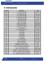
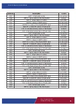
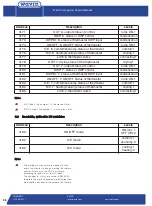
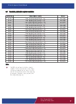
Address

Description [unit]

Value

4178

TH1 cooling set point [0.1 °C]

100..500

4179

TH1 heating set point [0.1 °C]

100..500

4180

TH1 economy set point [0.1 °C]

50..500

4181

TH2 cooling set point [0.1 °C]

100..500

4182

TH2 heating set point [0.1 °C]

100..500

4183

TH2 economy set point [0.1 °C]

50..500

4184

TH3 cooling set point [0.1 °C]

100..500

4185

TH3 heating set point [0.1 °C]

100..500

4186

TH3 economy set point [0.1 °C]

50..500

4187

TH4 cooling set point [0.1 °C]

100..500

4188

TH4 heating set point [0.1 °C]

100..500

4189

TH4 economy set point [0.1 °C]

50..500

4190

TH5 cooling set point [0.1 °C]

100..500

4191

TH5 heating set point [0.1 °C]

100..500

4192

TH5 economy set point [0.1 °C]

50..500

4193

TH6 cooling set point [0.1 °C]

100..500

4194

TH6 heating set point [0.1 °C]

100..500

4195

TH6 economy set point [0.1 °C]

50..500

4196

TH7 cooling set point [0.1 °C]

100..500

4197

TH7 heating set point [0.1 °C]

100..500

4198

TH7 economy set point [0.1 °C]

50..500

N

No

otte

es

s

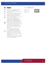
The BMS can continously write the set point 

variables. If not receive any news values then it 

will work according to the last status. The WTC

will start with the default values after connecting 

to the power. The default values can be set by

the configuration program. 

Design Manual 

Heating and Cooling systems


Summary of Contents for WTC-3

Page 1: ...on 2 0 Wavin Tempower Controls WTC 3 DRT 200 Intelligent Solutions for Heating Cooling Projects April 2010 version 2 0 Wavin Tempower Control WTC 3 DRT 200 FOR RESIDENTIAL COMMERCIAL AND INDUSTRIAL AP...

Page 2: ...gy saving mode economy mode 18 6 6 C Co om mp po on ne en nt ts s c co on nt tr ro oll 1 19 9 6 1 Mixing valve control 19 6 2 Room humidity control via dehumidifier 20 6 3 Pump control speed control p...

Page 3: ...pecialist planning in order to calculate and install the Wavin Tempower Heating and Cooling system 1 1 2 2 S Sc co op pe e This document contains technical information about the Wavin Heating and Cool...

Page 4: ...stallation must be installed by a suitably qualified engineer who is responsible for observing all relevant standards and regulations Only make changes or modifications as specified in this manual Pow...

Page 5: ...w o of f t th he e s sy ys st te em m The Wavin Tempower Control System consists of a base unit room thermostat sensors and actuators The base unit manages the operation of the actuator when the therm...

Page 6: ...reased lifetime The temperature and operation mode settings are indicated by LEDs The thermostat matches the size of standard electric boxes ensuring easy installation and fit The thermostat does not...

Page 7: ...rrent operating mode The default reference temperature for summer is 26 C and for winter is 21 C The temperature setting range from the reference temperature is 6 C default Temperature settings can be...

Page 8: ...ures the relative humidity in the room and sends information to the WTC 3 base unit In case of high humidity the WTC 3 will adjust the set temperature of thermostat increasing it step by step 4 4 6 Op...

Page 9: ...ms Room humidity control via a separate de humidifier Pump control frequency changer control Boiler chiller control Operation with optional timer Comfort Economy mode Master and Slave Setting option E...

Page 10: ...wer E MAIL info wavin com www wavincom TELEPHONE 31 38 429411 10 Wavin Temp Control Manual ower E MAIL info wavin com www wavincom TELEPHONE 31 38 429411 W Wiir riin ng g All wiring must comply with l...

Page 11: ...t Cooling reference temperature 26 C Heating reference temperature 20 C Economy set point 17 C Setting range 6 C Heating and Cooling Hysteresis 0 5 C M Ma as st te er r t th he er rm mo os st ta at t...

Page 12: ...h local electrical regulations and specifications Wavin recommends 18 AWG LVT or similar wire for all thermostat connections Strip all wires to 1 4 6 3 mm to ensure proper connection to thermostat ter...

Page 13: ...ust comply with local electrical codes and specifications Wavin recommends 18 AWG LVT or similar wire for all thermostat connections Strip all wires to 1 4 6 3 mm to ensure proper connection to thermo...

Page 14: ...tempera ture from these data in every room When the dew point reaches a predefined level the base unit will adjust the room thermostat to a higher temperature to prevent the condensation This gives th...

Page 15: ...ing systems 15 5 5 5 5 C Co on nn ne ec ct t a ac ct tu ua at to or rs s The WTC 3 has seven outputs to connect actuators Wavin actuators feature connectors for fast installation which simply plug in...

Page 16: ...ng mode two options D DR RT T 2 20 00 0 If the system is installed with a DRT 200 room thermostat then the requested mode can be changed at the master thermostat by pressing the heating or cooling but...

Page 17: ...et requires a two port motorised valve because of hydraulic reason balancing All motorised valves are controlled by the WTC 3 The base unit has a default program function to prevent unwanted temperatu...

Page 18: ...sting room thermostats can be connected to the base unit To activate the econo my function a separate switch should be connected to give an open close contact to the WTC 3 base unit When the Economy m...

Page 19: ...to keep an accurate temperature The PI regulation decreases over control and stopped the wave effect within the shortest time Note Any type of mixing valve controlled by 0 10V can be used The default...

Page 20: ...has an output to start and stop a dehumidifier unit based on the relative humidity at the master room at separately installed and connected humidity sensor The separately connected humidity sensor NO...

Page 21: ...ll actuators are closed down and the pump will stop Output eight on the unit switches on if the output of at least one control circuit switches on The output may be used for the activation of the pump...

Page 22: ...o ot te e Must install relay to get a potential free contact 6 6 4 4 B Bo oi il le er r c ch hi il ll le er r c co on nt tr ro ol l To start or stop the boiler chiller the same connection as the pump...

Page 23: ...occupy an analogue output on the WTC 3 Tt has a weekly program the periods of comfort and the economy mode temperature has to be set The thermostat must have open contact for comfort mode Tt must to...

Page 24: ...or Comfort economy and Heating Cooling inputs Mixing valve control P Pr ro og gr ra am m 2 2 6 x Analogue thermostat 5 dew point sensor Comfort economy and Heating Cooling inputs 7th output drying dem...

Page 25: ...ng Otherwise output 8 heating cooling demand will be continuously switched in cooling mode Control circuit 6 may be used only for heating Comfort Economy mode the energy saving mode may be adjusted on...

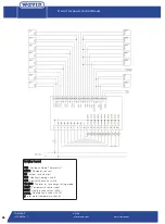
Page 26: ...Dr ra aw wiin ng g lle eg ge en nd d T TH H1 1 Analogue Room Thermostat 1 D DW WP P1 1 Dewpoint sensor 1 M M1 1 output for actuator 1 H H C C Heating Cooling switch C C E E Comfort Economy switch T T...

Page 27: ...itched in cooling mode Control circuit 6 may be used only for heating Comfort Economy mode the energy saving mode may be adjusted on C E input or via the communication channel Then the set point is gi...

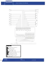
Page 28: ...aw wiin ng g lle eg ge en nd d T TH H1 1 Analogue Room Thermostat 1 D DW WP P1 1 Dewpoint sensor 1 M M1 1 output for actuator 1 H H C C Heating Cooling switch C C E E Comfort Economy switch T TH H E E...

Page 29: ...utput can supply 230V in every case when the WTC 3 receiving heating cooling demands from the room thermostats Output terminal strip points of control circuits out of use must be left unconnected Let...

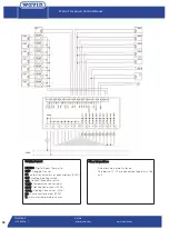
Page 30: ...Thermostat D DW WP P Dewpoint sensor M M1 1 output for actuators or dehumidifiers 230V H H C C Heating Cooling switch C C E E Comfort Economy switch T TE EM MP P Temperature sensor input H HE EA AT T...

Page 31: ...ct te ed d W WT TC C 64 t ty yp pe es s o of f w wiir re e 2 pcs twisted pair of wire example CAT5 UTP P Pr ro ot to oc co oll MODBUS RTU D Da at ta a e ex xc ch ha an ng ge e s sp pe ee ed d r ra at...

Page 32: ...4133 Dew point 0 1 C 0 500 4134 Type of unit DIP4 0 15 4136 TH1 measured temperature 0 1 C 0 500 4137 TH1 humidity 0 1 0 1000 4138 TH1 calculated dew point 0 1 C 0 500 4139 TH1 pot meter 0 1 C sign ma...

Page 33: ...1 C sign max max 4170 TH6 DWP resistance kohm 0 20000 4171 TH6 brightness lux 100 1000 4172 TH7 measured temperature 0 1 C 0 500 4173 TH7 humidity 0 1 0 1000 4174 TH7 calculated dew point 0 1 C 0 500...

Page 34: ...ensation 4112 1 output DO1 turns ON 1 4113 2 output DO2 turns ON 1 4114 3 output DO3 turns ON 1 4115 4 output DO4 turns ON 1 4116 5 output DO5 turns ON 1 4117 6 output DO6 turns ON 1 4118 7 output DO7...

Page 35: ...of the thermostat drying 1 4155 OUT 4 output status of control turns ON 1 4156 DWP 4 status of DWP control condensation 4157 DWP DI 4 status of thermostat DWP input condensation 4158 ON OFF 4 ON OFF...

Page 36: ...81 DWP DI 7 status of thermostat DWP input condensation 4182 ON OFF 7 ON OFF status of thermostat turns ON 1 4183 C E 7 comfort economy status of thermostat comfort 1 4184 H C 7 heating cooling status...

Page 37: ...0 1 C 100 500 4186 TH3 economy set point 0 1 C 50 500 4187 TH4 cooling set point 0 1 C 100 500 4188 TH4 heating set point 0 1 C 100 500 4189 TH4 economy set point 0 1 C 50 500 4190 TH5 cooling set poi...

Page 38: ...able to generate a full or a time limited license to a qualifying customers C Co on nt ta ac ct ts s alessandro_coletti wavin com zsolt banko wavin com To obtain the most recent version of the WTC 3 p...

Page 39: ...or cooling per thermostats Set reference temperature for economy mode per thermostats Set temperature range per thermostats Set mixed inlet temperature for heating Set mixed inlet temperature for cool...

Page 40: ...LEPHONE 31 38 429411 40 Wavin Temp Control Manual ower E MAIL info wavin com www wavincom TELEPHONE 31 38 429411 After you run the WTC 3 configurator exe file the following screen appear Under Edit Ou...

Page 41: ...gure Needs to be configure Change over is in progress Shortcut in the wire of dew point sensor The dew point sensor is not connected to the right input R Re em me ed dy y Check connection of electric...

Page 42: ...oling mode Check first in fully open cases 10V output the mixing valve is completly open as well Check the output voltage at 39 40 output plugs of WTC 3 It must be 0 10V Use a voltmeter If the voltmet...

Page 43: ...e Master side of MODBUS RTU or the BUS line end is not closed One or more thermostat are on the same address The DIP address must be the same what is set in the configuration program as a communicatio...

Page 44: ...s U UI I 1 piece water temperature or digital input voltage on the open contacts as digital input 3 5V maximum current on the closed contacts as digital input 1mA maximum temperature measurement sens...

Page 45: ...ng g may be set individually O Op pe er ra at tiin ng g e elle em me en nt ts s touch buttons F Fe ee ed db ba ac ck k LEDs brightness depending on room brightness C Co on nn ne ec ct tiio on n screw...

Page 46: ...ell 4 mm A Ac ct tu ua at to or r f fo or rc ce e 100 N 5 F Fllu uiid d t te em mp pe er ra at tu ur re e 0 100 C in dependance of the adapter even higher S St to or ra ag ge e t te em mp pe er ra at...

Page 47: ...ng ge e 0 70 C T Ty yp pe e o of f s se en ns so or r KTY 81 222 S Se en ns so or r c ca ap p Hermetically closed M Ma at te er riia all Galvanized CuNZ Cr VI free L Le en ng gh ht t 45 mm D Diia am...

Page 48: ...Wavin operates a programme of continuous product development and therefore reserves the right to modify or amend the specification of their product without notice All information in this publication...

Reviews: