Installation
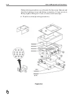
Refer to Figure 8-8 for the installation procedure.
1. Install new thermal fuse assembly (14) onto tank assembly.
Connect male connector to one of the connectors on cable
assembly (12).
2. Connect male connector of heater assembly (11) to the other
connector of the cable assembly.
3. Place clamp around thermal fuse (8) and reconnect to side of
tank assembly (4).
4. Reinstall top insulation blanket (3) around tank assembly (4).
5. Install and secure insulator plate (2) with screws.
6. Re-install wax system housing cover (1).
7. Re-install Printhead mounting hardware.
8. Connect 14-pin heater cable from controller to wax system.
9. Turn system
ON
and allow to heat.
10. Check indicators for proper operation of the heating circuits.
11. Resume normal operating procedures.
8-22
Removal/Replacement Procedures
Summary of Contents for 6100
Page 8: ...This page intentionally left blank...
Page 18: ...2 8 Application Design This page intentionally left blank...
Page 21: ...Dimensions Controller Application Design 2 11...
Page 22: ...Integrated Printhead Wax System 2 12 Application Design...
Page 55: ...Command Definitions 5 21...
Page 56: ...5 22 Command Definitions This page intentionally left blank...
Page 70: ...6 14 Installation Setup Figure 6 6...
Page 87: ...7 8 Service Figure 7 1...
Page 89: ...7 10 Service Figure 7 2...
Page 95: ...7 16 Service Figure 7 3...
Page 97: ...7 18 Service This page intentionally left blank...
Page 115: ...8 18 Removal Replacement Procedures Figure 8 7...
Page 125: ...8 28 Removal Replacement Procedures This page intentionally left blank...


