•
Note: Switch 4 must match ENCODER command setting for
print operation. See Command Definitions.
Installation & Setup
6-3
Switch Position
Front Port Baud Rate
Rear Port Baud Rate
0
38.4K
9600
1
38.4K
9600
2
38.4K
9600
3
38.4K
9600
4
38.4K
38.4K
5
38.4K
38.4K
6
38.4K
38.4K
7
38.4K
38.4K
8
9600
38.4K
9
9600
38.4K
A
9600
9600
B
9600
19.2K
C
19.2K
9600
D
19.2K
19.2K
E
19.2K
19.2K
F
19.2K
19.2K
Table 6 - 1 - Switch SW1 (CPU)
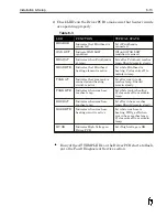
SWITCH NUMBER
DOWN
UP
1
ENCODER TYPE
OPEN COLLECTOR
TTL
2
NOT USED
3
NOT USED
4
FIRING PULSE
TIMING SOURCE
INTERNAL
OSCILLATOR
EXTERNAL SHAFT
ENCODER
5
NOT USED
6
REAR PORT
COMMUNICATIONS
SERIAL RS485
SERIAL RX232
Table 6-2 - Switch SW2 (CPU)
Summary of Contents for 6100
Page 8: ...This page intentionally left blank...
Page 18: ...2 8 Application Design This page intentionally left blank...
Page 21: ...Dimensions Controller Application Design 2 11...
Page 22: ...Integrated Printhead Wax System 2 12 Application Design...
Page 55: ...Command Definitions 5 21...
Page 56: ...5 22 Command Definitions This page intentionally left blank...
Page 70: ...6 14 Installation Setup Figure 6 6...
Page 87: ...7 8 Service Figure 7 1...
Page 89: ...7 10 Service Figure 7 2...
Page 95: ...7 16 Service Figure 7 3...
Page 97: ...7 18 Service This page intentionally left blank...
Page 115: ...8 18 Removal Replacement Procedures Figure 8 7...
Page 125: ...8 28 Removal Replacement Procedures This page intentionally left blank...


