Installation and Mounting
[17]
Figure 4-3: Maximum axial tilting
S: distance between measuring target and sensor head
a: maximal axial tilting angle < 2°
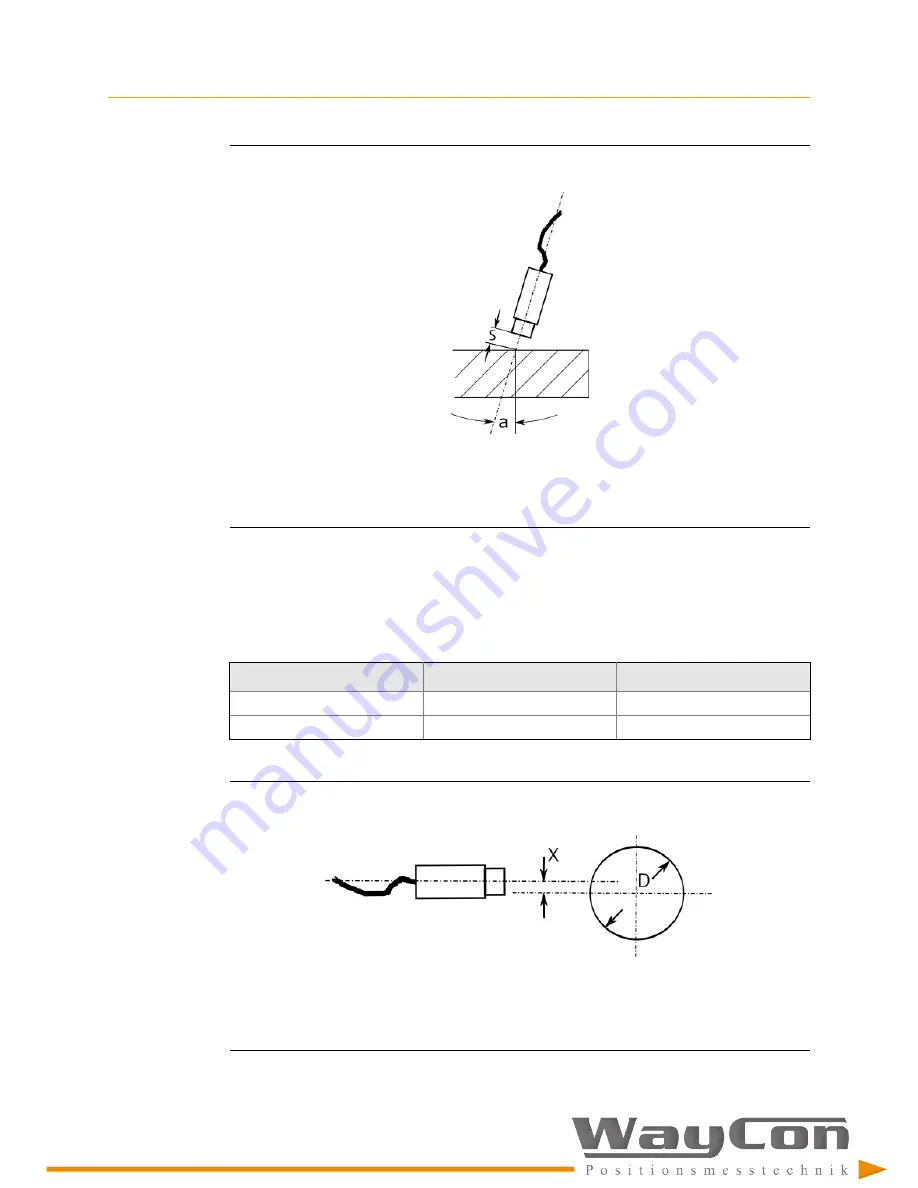
Maximum tangential offset
Ensure the maximum tangential offset matches the values in
shows
the definition of the tangential offset.
Table 4-1: Maximum tangential offset
Sensor type
Max. offset X
Shaft diameter D
EZ 105x
0.2 mm
≥ 20 mm
EZ 108x
0.5 mm
≥ 40 mm
Figure 4-4: Maximum tangential offset
X: maximal tangential offset
D: shaft diameter
Summary of Contents for EZ 105 Series
Page 4: ...Contents iv ...
Page 10: ...General 6 ...
Page 12: ...Safety instructions 8 Related information Environmental conditions ...
Page 16: ...Application and Design 12 ...

