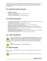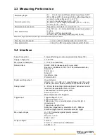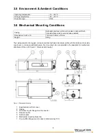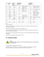
19
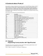
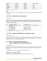
Scale factor
Resolution
Output
Unit of measure
SF1
1 mm
12.345
m
SF10
0,1 mm
123.45
Dm
SF1.0936
0,01 yard
13.500
Yard
SF3.28084
0,01 feet
40.501
feet
SF0.3937
1 inch
4.860
100 inch
SF-1
1 mm
-12.345
m
Table 3: Example of scale factor
Note:
Following a change in the scale factor, the settings for digital and/ or analog output and offset must be matched
accordingly!
4.3.12 SE
x
….display/set error mode [0/1/2]
Standard setting: 1
SE
allows you to configure how the digital switching output (alarm) and/or the analog output is to behave on
occurrence of an error message (E15, E16, E17, E18). Depending on the particular LLD application, different
reactions to an error message are possible. Available selection options are 0, 1 and 2 with the following effects
in the event of an error message:
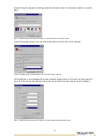
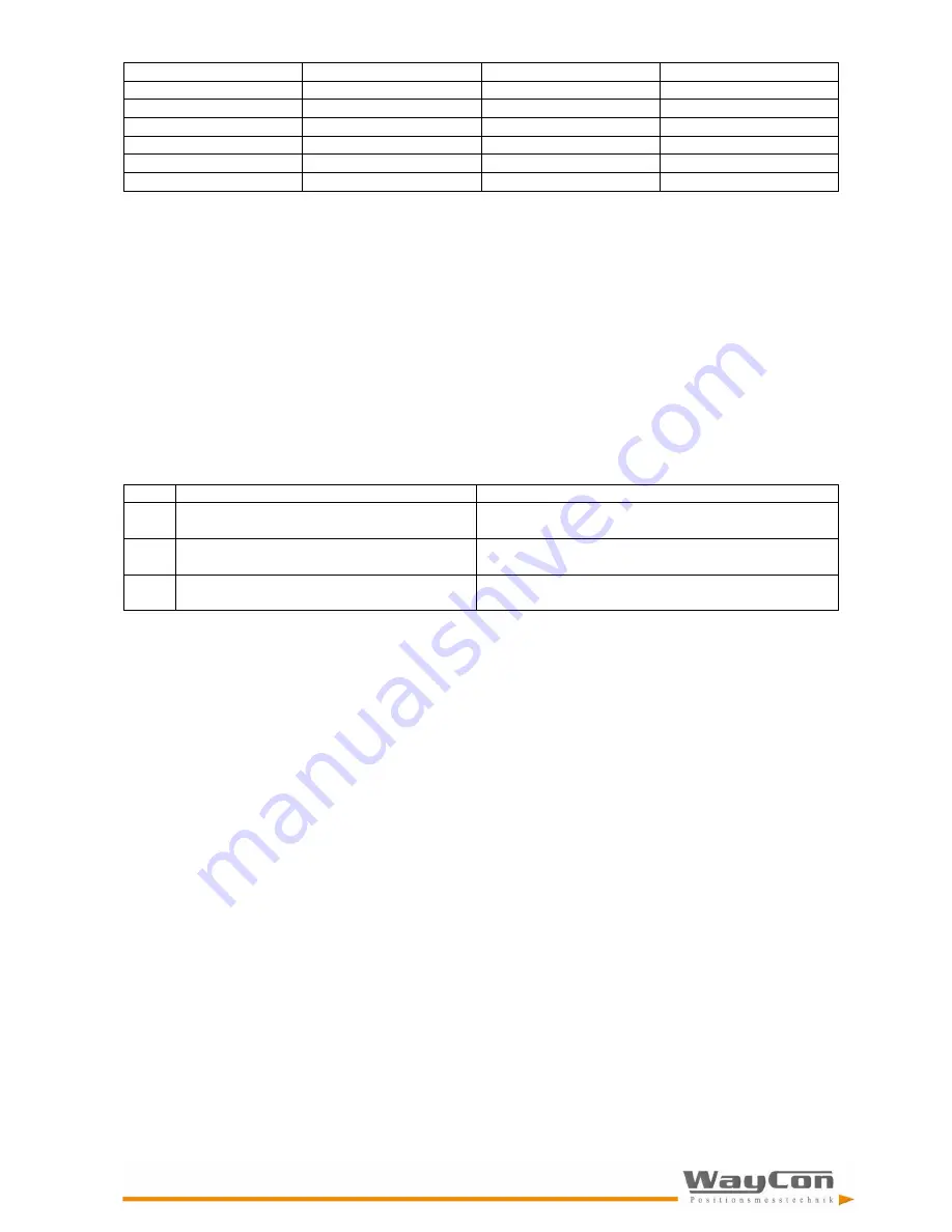
SE
Digital Output (ALARM)
Analog Output (I
out
)
0
ALARM – constant value of last valid
measurements
I
out
– constant value of last valid measurements
1
AH: Alarm = LOW
-AH: Alarm = High
RE > RB: I
out
= 3 mA
RE < RB: I
out
= 21 mA
2
AH: Alarm = High
-AH: Alarm = Low
RE > RB: I
out
= 21 mA
RE < RB: I
out
= 3 mA
Table 4: Digital switching output and analog output for SE = 0, 1 and 2
4.3.13 AC
x
.
x
…display/set ALARM center (switching output)
Standard setting: 1000
AC
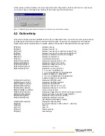
sets the beginning of the distance range, for which the switching output will be turned active. The length of
this active range can be set using the AW parameter. AC must be selected in keeping with the currently set SF
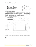
scale factor (refer to section 5.3 Digital switching output).
4.3.14 AHx.x…display/set ALARM hysteresis
(sign = Inverting yes/no, switching hysteresis)
Standard setting: +0.1
AH
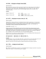
allows you to make parameter settings for the switching hysteresis at the beginning and the end point of the
active range of the switching output. AH must be selected so it is properly matched to the currently valid scale
factor (SF).
The mathematical sign of AH can be used to set an active state logic level:
Positive sign (“+”): active range is HIGH-active.
Negative sign (“-“): active range is LOW-active.
No sign setting means positively-signed (refer to section 5.3 Digital switching output).

