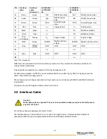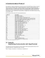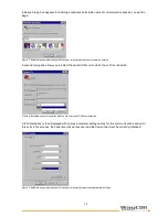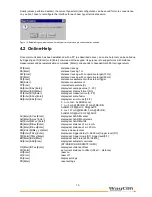
24
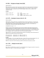
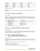
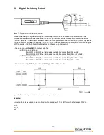
Example:
Parameter
Description
Default Wert
SA
average value
1
SD
display format
d
ST
measure time
0
SF
scale factor
1
SE
error mode
1
AC
ALARM center
20
AH
ALARM hysteresis
0.1
AW
ALARM width
10
RB
distance of I
out =
4mA
15
RE
distance of I
out =
20mA
25
RM
remove measurement
0 0 0
TD
trigger delay, trigger level
0 0
TM
trigger mode, trigger level
0 1
BR
baud rate
9600
AS
autostart command
ID
OF
distance offset
0
4.3.28 PR...Display settings
PR
resets all parameters (except for baud rate) to their standard settings.
Parameter
Description
Default Wert
SA
average value
1
SD
display format
d
ST
measure time
0
SF
scale factor
1
SE
error mode
1
AC
ALARM center
1000
AH
ALARM hysteresis
0.1
AW
ALARM width
100000
RB
distance of I
out =
4mA
1000
RE
distance of I
out =
20mA
2000
RM
remove measurement
0 0 0
TD
trigger delay, trigger level
0 0
TM
trigger mode, trigger level
0 1
BR
baud rate
9600
AS
autostart command
ID
OF
distance offset
0
5. Operating Modes
Make sure that all cable ends are protected against short circuit effects before you turn power supply on!
Connect cable terminals as required for the particular operating mode. To prevent short circuits, you should seal
unused cable ends! For starting up, a PC with RS232 or RS422 data interface and a terminal program such as
the hyper terminal are required. As part of preparative actions, the LLD must be properly installed in the
designated working site, oriented onto the target and kept in a stable position. The target to be measured should
preferentially have a homogeneous, white surface.
Caution: Do not use any retroreflectors!
The LLD provides a visible laser beam for greater convenience in alignment. This laser beam can easily be
turned on at the PC. Its visibility is conditional on the amount of ambient light present and on the type of surface
of the target to be measured.

