9
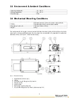
To protect the range finder’s optical surfaces from dust, physical contact, mechanical impacts, etc., the casing has
a special equalizer tube attached to it. This tube can be extended or removed
2
as necessary to meet the
customer’s operating needs. Please note that measurement cannot be guaranteed to function correctly if the
equalizer tube is removed by unqualified action!
2
consult your local distributor on this issue
Figure 2: Offset against zero-edge
The LLD’s zero-point is located 7 mm behind the outer surface of the front cover or 137 mm before the back
cover outside face respectively. This zero-point has been introduced for constructional design reasons. It can be
compensated with the help of parameter “OF“ (see section 4.3.23 „OF.......display/set distance offset“).
3.7 Electrical Mounting Conditions
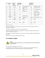
Located on the back cover is a connector terminal. A 12-pole round-type (flange mount) series 723 connector
from Binder has been selected for this purpose. It is sealed against the casing to comply with IP 65
requirements. This connector type guarantees optimized screening and a high IP degree. The required
counterpart is a cable jack (series 423 from Binder) with grading ring. A cable set with open ends is optionally
available.
Figure 3: View of LLD pin assignment

