INSTALLATION GUIDE
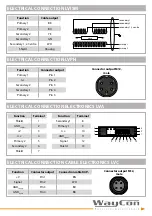
LVDT series LV, LVIT, LVIG, LVISM, LVPH
For further information please see the data sheet at www.waycon.biz/products/inductive-sensors-lvdt/
FIRST STEPS
WayCon Positionsmesstechnik GmbH would like to thank you for the trust you have placed in us and
our products. This manual will make you familiar with the installation and operation of our inductive
sensors LVDT. Please read this manual carefully before initial operation!
Unpacking and checking:
Carefully lift the device out of the box by grabbing the housing. After unpacking the device, check
it for any visible damage as a result of rough handling during the shipment. Check the delivery for
completeness.
If necessary consult the transportation company, or contact WayCon directly for further assistance.
GENERAL NOTES
• Mount the sensor before connecting the external electronics.
• The LV series can optionally be mounted with flange or foot clamps.
• Do not use the sensors near strong magnetic fields.
• Protect the electronics from moisture and humidity.
• Avoid lateral forces on the push rod.
• Do not press in the push rod beyond the specified total mechanical stroke.
• For a measuring range of 100 mm or more, the sensor housing must be additionally stabilised.
Otherwise the sensor may bend due to its own weight. In this case, we recommend using three
mounting brackets.
• For sensors without WayCon electronics, the minimum of the output signal is at the electrical centre
position. From there, half of the entire measuring range is in plus and half in minus (measuring range
start and measuring range end).
• The sensor is calibrated to the electronics supplied. The calibration protocol supplied loses its
validity as soon as the electronics are readjusted.
• Use the shortest possible cables between the sensor and the electronics.


