TECHNICAL DATA
INSTALLATION GUIDE
Linear potentiometer Series LZW2
For further information please see the data sheet at www.waycon.biz/products/linear-potentiometers/
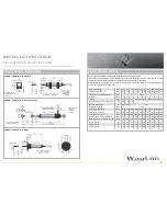
TECHNICAL DRAWING
Useful electrical stroke B: corresponds to the sensors measurement range
Theoretical electrical stroke C: actual length of the conductive path, that has to be longer than B, in order
to get a valid electrical signal at the start and end point of the measurement range.
When calibrating the transducer, be careful to set the stroke so that the output does not drop below 1%
or rise above 99% of the voltage level.
LZW2-S: installation with brackets
LZW2-A: installation with rod end bearings
rod end bearing SND005
(included in delivery)
rod end bearing
SND004
(included in
delivery)
bracket STA075
(2 pieces included
in delivery)
LZW2-F: installation with flange
Measurement range
[mm]
25
50
75
100
125
150
175
200
250
300
Electrical stroke (B) +1/-0
[mm]
25
50
75
100
125
150
175
200
250
300
Theoretical electrical Stroke (C) ±1
[mm]
B +1
Resistance
1
2
3
4
5
6
7
8
10
12
Linearity
[±%]
0.2
0.1
0.1
0.1
0.05 0.05 0.05 0.05 0.05 0.05
Max. dissipation at 40°C (0 W at 120°C)
[W]
0.8
1.6
2.8
3
Maximum power supply
[V]
20
40
60
Mechanical stroke (D)
[mm]
B +5
Case length (A) LZW1-S
[mm]
83.5 108.5 133.5 158.5 183.5 208.5 233.5 258.5 308.5 358.5
Case length (A) LZW1-A
[mm]
110
135
160
185
210
235
260
285
335
385
Case length (A) LZW1-F
[mm]
83.5 108.5 133.5 158.5 183.5 208.5 233.5 258.5 308.5 358.5
Recommended distance brackets (E)
[mm]
47
72
97
122
147
172
197
222
272
322
Minimum distance rod end bearings (E)
[mm]
163
188
213
238
263
288
313
338
388
438
Weight LZW1-S
[g]
90
105
130
160
175
190
205
215
245
275
Weight LZW1-A
[g]
110
125
150
180
195
210
225
235
260
285
Weight LZW1-F
[g]
100
115
140
170
185
200
215
225
255
280
[kOhm]


