- 21 -
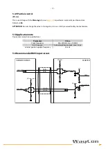
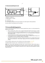
6.1 Recommended input circuit
+V encoder = +5 VDC ±5%
+V load = +5 VDC ±5% typically
I
out
= 40 mA max.
Max. cable length = 10 m
The max. frequency allowed for the AB signals depends on the cable length and the applied load.
Thermal and short-circuit protections are not provided.
7. Error and fault diagnostics
In case of wrong alignment between the sensor and the magnetic tape, at power on or during operation the
following errors may occur:
•
When switching on the system an alarm is triggered through the dedicated bit: the tape is not read
correctly. This may be due to one of the following reasons: the tape is not mounted properly; the
tape’s magnetic surface is damaged somewhere; the sensor is not working properly causing invalid
data to be transmitted.
As soon as the sensor is aligned correctly the error bit switches to high logic level.
•
During operation an alarm is triggered through the dedicated bit: as previously stated, the tape is not
read correctly. This may be due to one of the reasons listed above.
Furthermore, the alarm may be caused by a frequency error: the sensor is travelling too fast on the
tape. The last valid position is “frozen” (kept in memory) until the next valid position is detected on
the tape.
In the SSI interface, the device status is transmitted via the error bit, see section
In the BiSS interface, the device status is transmitted via the nE bit, see section
NOTE:
When the error bit has high logic level (normal status, no alarm active), this means that the sensor is
working properly and both the absolute position information and the incremental signals are output correctly.
Please note that the error bit is intended to communicate the status of both the absolute interface and the AB
incremental signals.
DC/DC
Encoder
circuit
+VDD
0 V
+V encoder
+V load
+V/2
INPUT
Summary of Contents for MXS2
Page 1: ...Magnetic Scale MXS2 Manual...


