
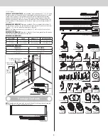
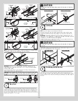
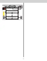

Center
hinge(s)
Left graduated end hinge
with short stem track roller
Right graduated end hinge
with short stem track roller
Center
hinge(s)
Right double graduated
end hinge with long stem
track roller
1/4”-20 x 11/16” Self drilling screw locations
1/4”-20 x 11/16” Self drilling screw locations
Left double graduated end
hinge with long stem track
roller
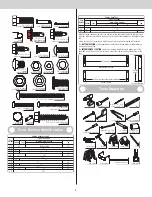
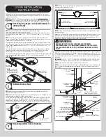
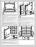
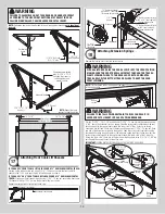
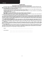
Stacking Top Section
12
Place the top section in the opening. Install a nail to prevent the top section from falling
backwards. Now, flip up the hinge leaves, hold tight against section, and fasten center hinges
first and end hinges last (refer to step, Stacking Sections). Vertical track alignment is critical.
Position flag angle or wall angle between 1-11/16” (43 mm) to 1-3/4” (44 mm) from the
edge of the door; tighten the bottom lag screw. Flag angles must be parallel to the door sec-
tions. Repeat for other side.
IMPORTANT:
THE DIMENSION BETWEEN THE FLAG ANGLES OR WALL ANGLES MUST BE
DOOR WIDTH PLUS 3-3/8” (86MM) TO 3-1/2” (89 MM) FOR SMOOTH, SAFE DOOR OPERA-
TION.
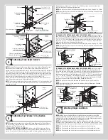
FOR QUICK INSTALL TRACK:
Complete the vertical track installation by securing the jamb
bracket(s) and tightening the other lag screws. Repeat for other side.
FOR FULLY ADJUSTABLE TRACK OR RIVETED TRACK:
Complete the vertical track instal-
lation by securing the jamb bracket(s) and tightening the other lag screws. Push the vertical
track against the track rollers so that the track rollers are touching the deepest part of the
curved side of the track; tighten all the track bolts and nuts. Repeat for other side.
FOR ANGLE MOUNT TRACK:
Complete the vertical track installation by securing the jamb
bracket(s) and or tightening the other lag screws. Push the vertical track against the track
rollers so that the track rollers are touching the deepest part of the curved side of the vertical
track, as shown. Repeat for other side.
Top section
Top
section
Nail
Door width
+ 3-3/8” to 3-1/2”
1-11/16”
to 1-3/4”
Flag
angle
Vertical track
against track rollers
Flag angle or
wallangle assembly
Top of flag angle or
Top of wallangle assembly
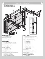
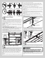
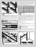
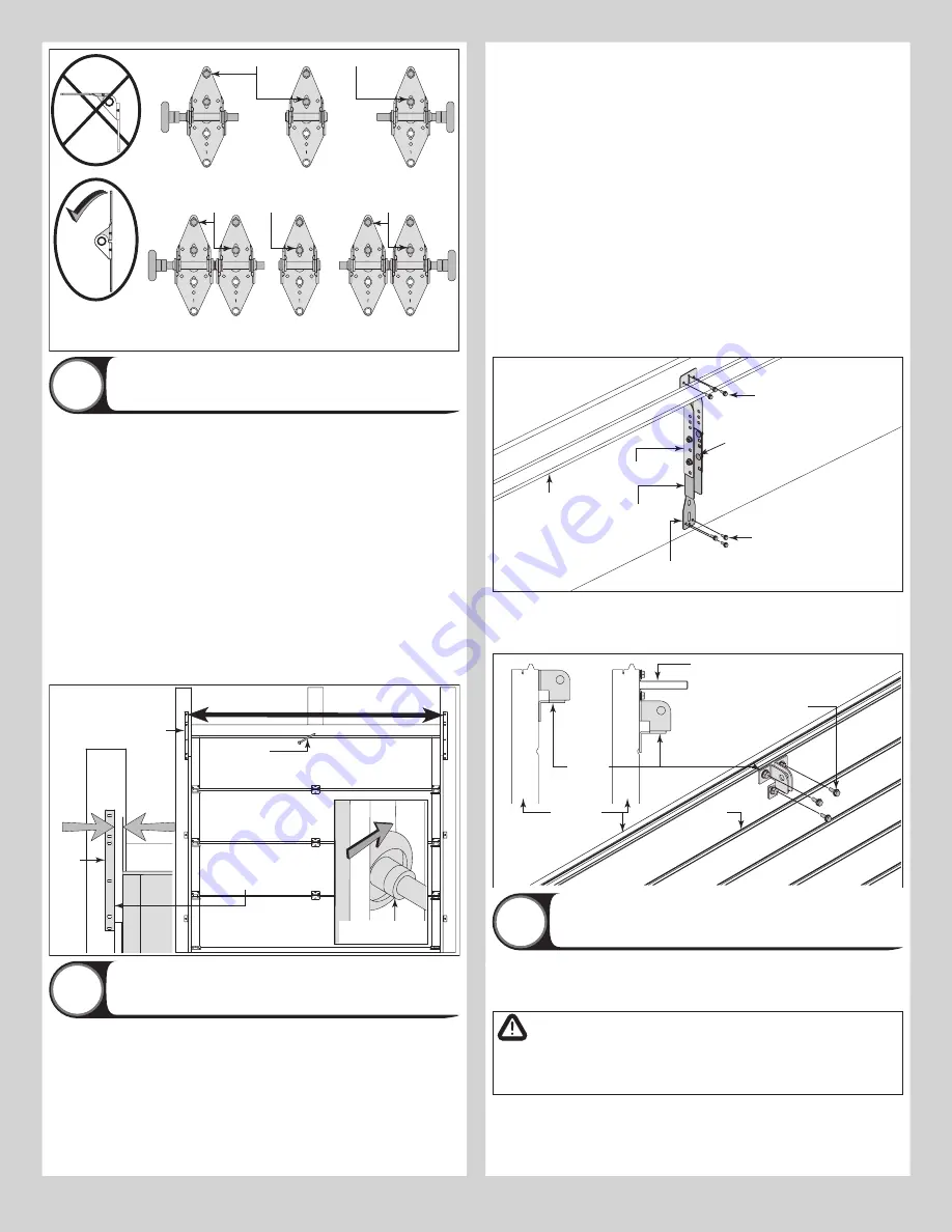
Attaching Drawbar Operator Bracket
13
IMPORTANT:
WHEN CONNECTING A TROLLEY TYPE GARAGE DOOR OPENER TO THIS DOOR,
A WAYNE DALTON OPERATOR/ TROLLEY BRACKET MUST BE SECURELY ATTACHED TO
THE TOP SECTION OF THE DOOR IF ONE HAS BEEN PROVIDED, ALONG WITH ANY STRUTS
PROVIDED WITH THE DOOR (IF A WAYNE DALTON OPERATOR/ TROLLEY BRACKET WAS NOT
PROVIDED WITH YOUR DOOR, THAN USE THE ONE PROVIDED BY YOUR OPERATOR MANU-
FACTURER). THE INSTALLATION OF THE OPERATOR MUST BE ACCORDING TO MANUFAC-
TURER’S INSTRUCTIONS AND FORCE SETTINGS MUST BE ADJUSTED PROPERLY.
NOTE:
For retro fit applications, the drawbar operator bracket must be aligned with an exist-
ing operator.
NOTE:
Refer to illustrations to determine which drawbar operator bracket were supplied with
your door. Follow the corresponding step below:
Place the bottom half inside the top half and flush against the inside surface of the top
section. Adjust both the top and bottom halves out as far apart as possible on the section
surface. Secure the drawbar operator bracket bottom half and the top half together using (4)
5/16” - 18 x 1/2” carriage bolts and (4) 5/16” - 18 flange hex nuts.
NOTE:
Install the 5/16” - 18 x 1/2” carriage bolts and the 5/16” - 18 flange hex nuts as far
apart as possible, prior to securing both top and bottom halves together.
Now, locate the center of the top section and align the center of the holes in the drawbar op-
erator bracket assembly with the top section center line. Align the drawbar operator bracket
assembly vertically.
NOTE:
For retro fit applications, the drawbar operator bracket assembly must be aligned with
an existing operator.
Slide the top halve of the drawbar operator bracket assembly under the strut, keeping the
drawbar operator bracket assembly aligned with the center line. Remove the strut’s screws, if
necessary and attach to the top section (through strut if necessary) using (3) 1/4” - 20 x 7/8"
self drilling screws.
NOTE:
If your door lacks a strut on the top section, ignore the previous paragraph.
Attach the bottom halve of the drawbar operator bracket to the section surface using (3) 1/4”
- 20 x 7/8” self drilling screws.
NOTE:
When attaching drawbar operator bracket to top section with strut, apply additional
pressure to thread into the strut.
(3) 1/4”- 20 x 7/8”
Self-drilling screws
(4) 5/16”- 18 x 1/2”
Carriage bolts and
(4) 5/16”- 18 flange
hex nuts
(3) 1/4” -20 x 7/8”
Self-drilling screws
Bottom half
Top half
Strut
Drawbar
operator bracket
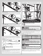
Locate the center of the top section. Position the drawbar operator bracket under the strut
(if applicable) or align the drawbar operator bracket top edge with the top edge of the top
section, as shown. Attach the drawbar operator bracket using (3) 1/4” - 20 x 7/8” self-drilling
screws (as shown).
(3) 1/4”- 20 x 7/8”
Self-drilling screws
Pin
stripes
Top section
Strut
Drawbar
operator
bracket
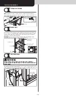
Attaching Horizontal Tracks
14
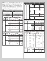
NOTE:
Depending on your door, you may have Quick Install Flag Angles, Fully Adjustable Flag
Angles, Riveted Vertical Track Assemblies or you may have Angle Mount Vertical Track As-
semblies. Refer to Package Contents / Breakdown of Parts, to determine which Flag Angles /
Vertical Track Assemblies you have.
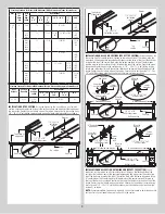
WARNING
DO NOT RAISE DOOR UNTIL HORIZONTAL TRACKS ARE SECURED AT
REAR, AS OUTLINED IN STEP, REAR BACK HANGS, OR DOOR COULD FALL
FROM OVERHEAD POSITION CAUSING SEVERE OR FATAL INJURY.
IF YOU HAVE QUICK INSTALL FLAG ANGLES:
To install horizontal track, place the curved
end over the top track roller of the top section. Align key slot of the horizontal track with the
Quick Install tab of the flag angle. Push curved portion of horizontal track down to lock in
place.
12


