
Important Safety Instructions
DEFINITION OF KEY WORDS USED IN THIS MANUAL:
WARNING
INDICATES A POTENTIALLY HAZARDOUS SITUATION WHICH; IF NOT
AVOIDED, COULD RESULT IN SEVERE OR FATAL INJURY.
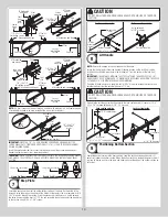
CAUTION
PROPERTY DAMAGE OR INJURY CAN RESULT FROM FAILURE TO FOLLOW
INSTRUCTIONS.
IMPORTANT:
REQUIRED STEP FOR SAFE AND PROPER DOOR OPERATION.
NOTE:
Information assuring proper installation of the door.
READ THESE INSTRUCTIONS CAREFULLY BEFORE ATTEMPTING INSTALLATION. IF
IN QUESTION ABOUT ANY OF THE PROCEDURES, DO NOT PERFORM THE WORK.
INSTEAD, HAVE A TRAINED DOOR SYSTEMS TECHNICIAN DO THE INSTALLATION OR
REPAIRS.
1.
READ AND FOLLOW ALL INSTALLATION INSTRUCTIONS.
2.
Wear protective gloves during installation to avoid possible cuts from sharp metal
edges.
3.
It is always recommended to wear eye protection when using tools, otherwise eye
injury could result.
4.
Avoid installing your new door on windy days. Door could fall during the installation
causing severe or fatal injury.
5.
Doors 12’-0” wide and over should be installed by two persons, to avoid possible
injury.
6.
Operate door only when it is properly adjusted and free from obstructions.
7.
If a door becomes hard to operate, inoperative or is damaged, immediately have
necessary adjustments and/ or repairs made by a trained door system technician using
proper tools and instructions.
8.
DO NOT stand or walk under a moving door, or permit anybody to stand or walk under
an electrically operated door.
9.
DO NOT place fingers or hands into open section joints when closing a door. Use lift
handles/ gripping points when operating door manually.
10.
DO NOT permit children to operate garage door or door controls. Severe or fatal injury
could result should the child become entrapped between the door and the floor.
11.
Due to constant extreme spring tension, do not attempt any adjustment, repair or
alteration to any part of the door, especially to springs, spring brackets, bottom corner
brackets, fasteners, counterbalance lift cables or supports. To avoid possible severe or
fatal injury, have any such work performed by a trained door systems technician using
proper tools and instructions.
12.
On electrically operated doors, pull down ropes must be removed and locks must be
removed or made inoperative in the open (unlocked) position.
13.
Top section of door may need to be reinforced when attaching an electric opener.
Check door and/ or opener manufacturer’s instructions.
14.
Visually inspect door and hardware monthly for worn and or broken parts. Check to
ensure door operates freely.
15.
Test electric opener’s safety features monthly, following opener manufacturer’s instruc-
tions.
16.
NEVER hang tools, bicycles, hoses, clothing or anything else from horizontal tracks.
Track systems are not intended or designed to support extra weight.
17.
This door may not meet the building code wind load requirements in your area. For
your safety, you will need to check with your local building official for wind load code
requirements and building permit information.
18.
For windloaded doors, the wind performance is achieved via the entire door system
and component substitution is not authorized without express permission by Wayne
Dalton.
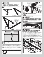
NOTE:
It is recommended that 5/16” lag screws are pilot drilled using a 3/16” drill bit, prior
to fastening.
CAUTION
IF ANY PART OF THE DOOR IS TO BE INSTALLED ONTO PRESERVATIVE-
TREATED WOOD, PTFE-COATED OR STAINLESS STEEL FASTENERS MUST BE
OBTAINED AND USED. REPLACEMENT FASTENERS MUST BE OF AT LEAST
EQUAL STRENGTH AND SIZE AS ORIGINAL FASTENERS. IF THE ORIGINAL
FASTENER WAS RED-HEAD, THE REPLACEMENT FASTENER MUST BE RED-
HEAD ALSO. CONTACT WAYNE DALTON FOR FASTENER STRENGTH VALUES IF
NEEDED.
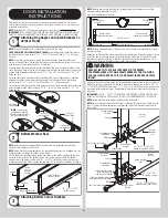
WARNING
IMPACT GUNS ARE NOT RECOMMENDED. WHEN INSTALLING 5/16” LAG
SCREWS USING AN ELECTRIC DRILL/ DRIVER, THE DRILL/ DRIVERS
CLUTCH MUST BE SET TO DELIVER NO MORE THAN 200 IN-LBS OF
TORQUE. FASTENER FAILURE COULD OCCUR AT HIGHER SETTINGS.
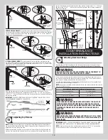
IMPORTANT:
RIGHT AND LEFT HAND IS DETERMINED INSIDE THE BUILDING LOOKING OUT.
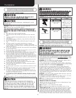
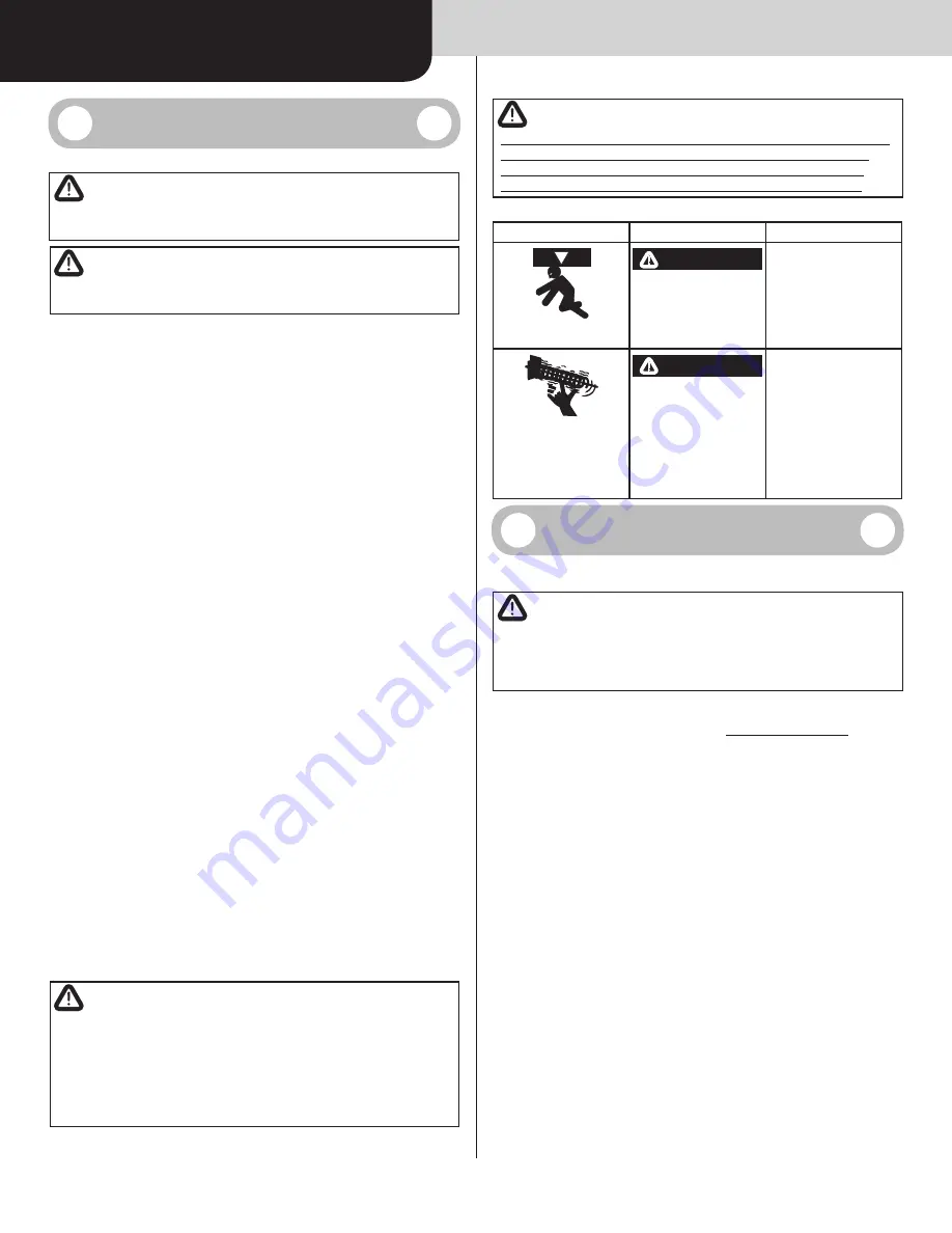
Potential Hazard
Effect
Prevention
Moving door
WARNING
Could result in Death or
Serious Injury
Keep people clear of opening
while Door is moving.
Do
NOT
allow children to play
with the Door Opener.
Do
NOT
operate a Door that
jams or one that has a broken
spring.
High tension spring
WARNING
Could result in Death or
Serious Injury
Do
NOT
try to remove, install,
repair or adjust springs or
anything to which door spring
parts are fastened, such as,
wood blocks, steel brackets,
cables or other like items.
Installations, repairs and
adjustments must be done by
a trained door system techni-
cian using proper tools and
instructions.
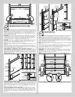
Removing an Existing Door
and Preparing the Opening
IMPORTANT:
COUNTERBALANCE SPRING TENSION MUST ALWAYS BE RELEASED BEFORE
ANY ATTEMPT IS MADE TO START REMOVING AN EXISTING DOOR.
WARNING
A POWERFUL SPRING RELEASING ITS ENERGY SUDDENLY CAN CAUSE
SEVERE OR FATAL INJURY. TO AVOID INJURY, HAVE A TRAINED DOOR
SYSTEMS TECHNICIAN, USING PROPER TOOLS AND INSTRUCTIONS,
RELEASE THE SPRING TENSION.
To avoid possible injury and to insure proper installation, it's highly recommended that you
read and fully understand the complete instructions on removing an Existing Door & Prepar-
ing the Opening. These are available for download at
www.Wayne-Dalton.com
or at your
local Wayne Dalton Sales Center.
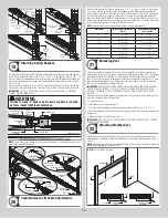
IMPORTANT:
IF YOU JUST REMOVED YOUR EXISTING DOOR OR YOU ARE INSTALLING A
NEW DOOR, COMPLETE ALL STEPS IN PREPARING THE OPENING.
To ensure secure mounting of track brackets, side and center brackets, or steel angles to
new or retro-fit construction, it is recommended to follow the procedures outlined in DASMA
technical data sheets #156, #161 and #164 at
www.dasma.com
.
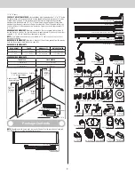
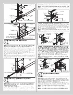
The inside perimeter of your garage door opening should be framed with wood jamb
and header material. The jambs and header must be securely fastened to sound framing
members. It is recommended that 2” x 6” lumber be used. The jambs must be plumb and
the header level. The jambs should extend a minimum of 12” (305 mm) above the top of
the opening for TorqueMaster
®
counterbalance systems. For low headroom applications, the
jambs should extend to the ceiling height. Minimum side clearance required, from the open-
ing to the wall, is 3-1/2” (89 mm).
IMPORTANT:
CLOSELY INSPECT JAMBS, HEADER AND MOUNTING SURFACE. ANY WOOD
FOUND NOT TO BE SOUND, MUST BE REPLACED.
For TorqueMaster
®
counterbalance systems, a suitable mounting surface (2” x 6”) must be
firmly attached to the wall, above the header at the center of the opening.
NOTE:
Drill a 3/16” pilot hole in the mounting surface to avoid splitting the lumber. Do not
attach the mounting surface with nails.
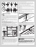
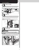
WEATHERSTRIPS (MAY NOT BE INCLUDED):
Depending on the size of your door, you may have to cut or trim the weatherstrips (if neces-
sary) to properly fit into the header and jambs.
NOTE:
If nailing product at 40°F or below, pre-drilling is required.
NOTE:
Do not permanently attach weatherstrips to the header and jambs at this time.
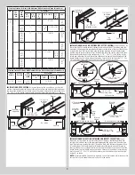
FOR QUICK INSTALL TRACK:
For the header, align the weatherstrip with the inside edge
of the header and temporarily secure it to the header with equally spaced nails. Starting
at either side of the jamb, fit the weatherstrip up tight against the temporarily attached
weatherstrip in the header and flush with the inside edge of the jamb. Temporarily secure
the weatherstrip with equally spaced nails. Repeat for other side. This will keep the bottom
section from falling out of the opening during installation. Equally space nails approximately
2
Pre-Installation


