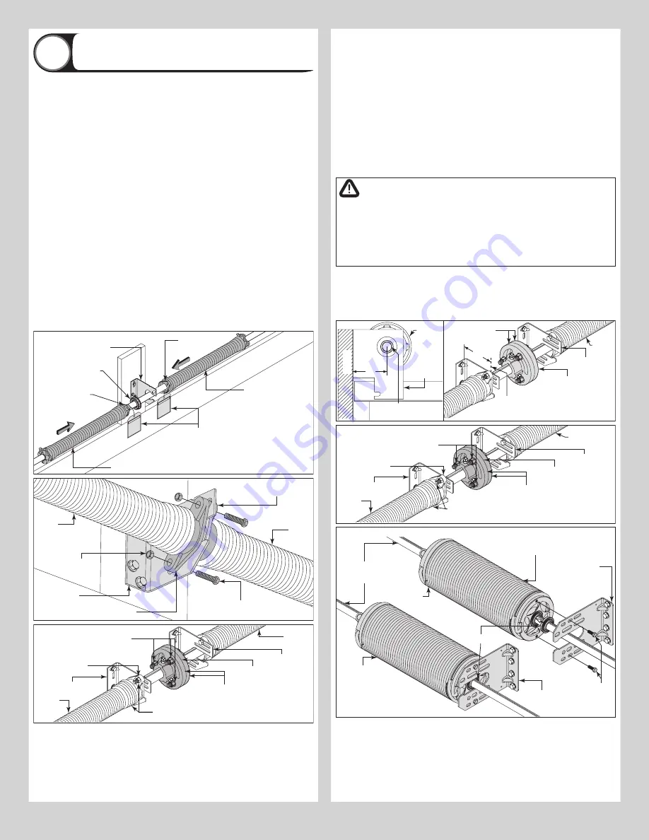
Attaching Springs to Center Bracket
23
NOTE:
Refer to Package Contents / Breakdown of Parts, to determine which Center
Bracket(s) came with your door.
NOTE:
Refer to Package Contents / Breakdown of Parts, to determine if your door came with
a coupler assembly.
IMPORTANT:
THE SPRING WARNING TAG(S) SUPPLIED MUST BE SECURELY ATTACHED
TO THE STATIONARY SPRING CONE(S) IN PLAIN VIEW. SHOULD A REPLACEMENT SPRING
WARNING TAG BE REQUIRED, CONTACT WAYNE DALTON FOR FREE REPLACEMENTS.
NOTE:
Measure the diameter of your springs. If your spring diameter is 3-3/4”, the springs
do not share center brackets. If your spring diameter is either 2” or 2-5/8”, then two springs
will share the same center bracket, unless a coupler assembly is provided.
IF YOU DON’T HAVE A COUPLER ASSEMBLY:
Slide center bracket bearing into the spring.
Align the stationary spring cone(s) with the holes in the center bracket. Secure the torsion
spring(s) to the center bracket with (2) 3/8” - 16 x 1-1/2” hex head bolts and (2) 3/8” - 16
nuts.
IMPORTANT:
NEVER USE MORE THAN ONE BEARING WHEN ATTACHING TWO SPRINGS TO
ONE CENTER BRACKET.
IF YOU HAVE A COUPLER ASSEMBLY:
Slide center bracket bearing into the spring. Align
the stationary spring cone with the holes in the center bracket. Secure the torsion spring to
the center bracket with (2) 3/8” - 16 x 1-1/2” hex head bolts and (2) 3/8” - 16 nuts. Repeat
the same process for the other center bearing bracket.
At the middle of the two center bearing brackets, re-assemble the coupler assembly by
loosely fastening the coupler halves together using the (3) 3/8” - 16 x 1-1/2” hex head
screws, (6) 3/8” washers, (3) 3/8” lock washers and the (3) 3/8” - 16 hex nuts, previously
removed.
NOTE:
Ensure both torsion keyed shafts have equal amounts of the shafts extending from
each end bearing bracket.
Typical center
bracket bearing
Stationary
spring cone
Typical center
bracket
Stationary
spring cone
Torsion spring
Spring
warning tags
Torsion spring
Typical center
bracket
Stationary spring cone
(2) 3/8”-16 x 1-1/2”
Hex head bolts
(2) 3/8”-16
Nuts
Torsion
spring
Torsion
spring
Stationary
spring cone
Coupler halves
Coupler
assembly
(3) 3/8” - 16 x 1-3/4”
hex head screws and
(3) 3/8” - 16 Hex nuts
Stationary
spring cone
Torsion
spring
(2) 3/8”-16 x 1-1/2” Hex head
bolts and (2) 3/8”-16 Hex nuts
Torsion
spring
Center bracket
Center
bracket
NOTE:
Refer to Package Contents / Breakdown of Parts, to determine which Center
Bracket(s) came with your door.
NOTE:
Refer to Package Contents / Breakdown of Parts, to determine if your door came with
a coupler assembly.
IMPORTANT:
THE SPRING WARNING TAG(S) SUPPLIED MUST BE SECURELY ATTACHED
TO THE STATIONARY SPRING CONE(S) IN PLAIN VIEW. SHOULD A REPLACEMENT SPRING
WARNING TAG BE REQUIRED, CONTACT WAYNE DALTON FOR FREE REPLACEMENTS.
FOR SPRINGS UP TO 3-3/4” ID AND IF YOU DON’T HAVE A COUPLER ASSEMBLY:
Slide
center bearing into the spring (if applicable). Align the stationary spring cone(s) with the holes
in the center bracket assembly. Secure the torsion spring(s) to the center bracket assembly
with (2) 3/8” - 16 x 1-1/2” hex head bolts and (2) 3/8” - 16 nuts.
IF YOU HAVE A COUPLER ASSEMBLY:
Slide the center bearing into the spring. Align the
stationary spring cone with the holes in the center bearing bracket.
NOTE:
Prior to attaching the torsion spring(s) to the center bracket(s), the torsion shaft /
torsion keyed shafts have to be at the same elevation as the bearing in the end bearing
brackets. Slide the torsion shaft / torsion keyed shafts out to the correct shaft centerline from
the jambs before tightening the spring assembly fasteners.
FOR SPRINGS UP TO 3-3/4” ID:
Secure the torsion spring to the center bracket with (2)
3/8” - 16 x 1-1/2” hex head bolts and (2) 3/8” - 16 nuts. Repeat the same process for the
other center bearing bracket.
FOR 6” AND DUPLEX SPRINGS:
Secure the torsion spring and the flange bearing to the
center bracket using (2) 3/8” - 16 x 1” Hex head bolts, as shown.
WARNING
FOR DUPLEX SPRINGS, YOU MUST ENSURE THE ASSEMBLY BOLTS
GO THROUGH THE CENTER BRACKET AND INNER SPRING CONE AND
THREAD INTO THE OUTER SPRING CONE AS SHOWN. FAILURE TO
ENSURE THE BOLTS ARE SECURING BOTH THE INNER AND OUTER
SPRING CONES TO THE CENTER BRACKET CAN RESULT IN SUDDEN
SPRING TENSION RELEASE, CAUSING SEVERE OR FATAL INJURY.
At the middle of the two center bearing brackets, loosely re-assemble the coupler assembly
by fastening the coupler halves together using the (3) 3/8” - 16 x 1-3/4” hex head screws
and the (3) 3/8” - 16 nylon hex lock nuts, as shown.
NOTE:
Ensure both torsion keyed shafts have equal amounts of the shafts extending from
each end bearing brackets.
Coupler
halves
Coupler
assembly
End bearing
bracket
Torsion shaft or
Torsion keyed shafts
Torsion
spring
Cable
drum
Center
bracket
=
Surface
=
Torsion shaft(s)
centerline
Coupler halves
Coupler
assembly
(3) 3/8” - 16 x 1-3/4” hex head
screws and (3) 3/8” - 16 Hex nuts
Stationary
spring cone
Torsion
spring
(2) 3/8”-16 x 1-1/2”
Hex head bolts and (2)
3/8”-16 Hex nuts
Torsion
spring
Center bracket
Center
bracket
Up To 3-3/4” Springs Applications
Torsion shaft /
Torsion keyed
shaft(s)
3/8” - 16 x 1”
Hex head
screws
Outer torsion
spring assembly
Center bracket
Outer torsion
spring assembly
Flange bearing
Center bracket
6” ID Springs
NOTE:
This type of torsion spring
assembly has just an outer spring,
no inner spring assembly.
6” Springs Applications
10


