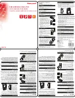
anchors (by others). This installation will require the 1/2” anchors to be secured to the build-
ing and then secure the brackets to the anchors, as shown.
NOTE:
Pre-Drill 1/2” pilot holes into the pre-cast for the 1/2” x 3” sleeve anchors.
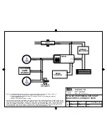
FOR BLOCK CONSTRUCTION:
Attach perforated angle 18” long to center bracket(s) using
(2) 3/8” x 1-1/4” bolts and (2) 3/8”nuts. Chamfer angle to clear top section high arc. Secure
center bracket(s) and perforated angle to block using (4) 3/8” x 2-1/2” sleeve anchors, as
shown.
WARNING
DO NOT USE SLEEVE ANCHORS ON HOLLOW BLOCK.
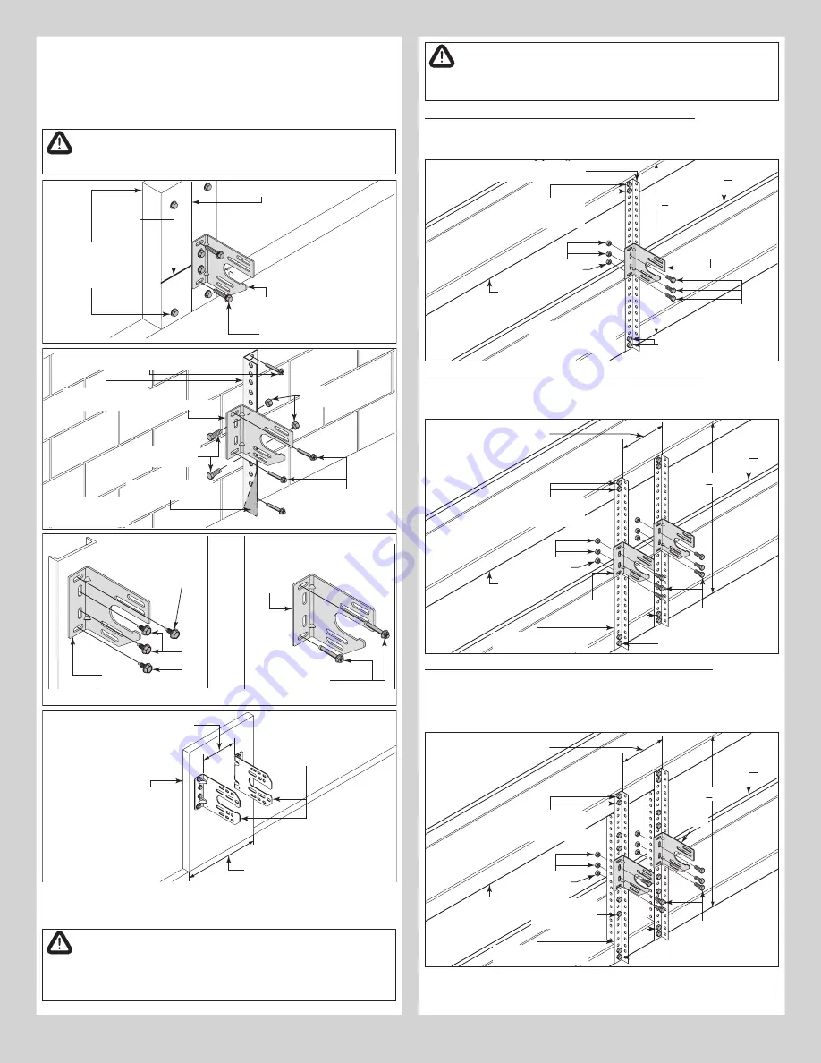
Vertical line
Spring mounting pad (2”
X 6“) White Pine or
denser. Secured with a
minimum of (4) 5/16” x
4” lag bolts into header.
Horizontal
line
Center
bracket
5/16” x 1-5/8” Hex
head lag screws
Wood
NOTE:
Actual center bracket may
vary, see breakdown of parts.
(2) 3/8” x 1-1/4”
Hex bolts
Center bracket
(2) 3/8”
Hex nuts
Chamfered to clear
door high-arc.
Sleeve anchors (3/8” x
2-1/2”) positioned in
the top and bottom slot
of center bracket.
(18” length) Perforated
angle
Concrete
Blocks
NOTE:
All (4) sleeve anchors (3/8” x 2-1/2”) must
be positioned a minimum of 1” from block edge.
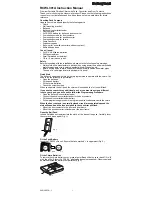
NOTE:
Actual center
bracket may vary, see
breakdown of parts.
Center
bracket
(Steel Jambs) (4) 5/16” x 1”
Self drilling screws
Steel
Pre-Cast
Center
bracket
(Pre-cast) (2) 1/2” x 4”
Sleeve anchors
NOTE:
Must secure
sleeve anchors first, then
attach center brackets to
sleeve anchors.
NOTE:
Actual center bracket may vary, see breakdown of parts.
12”
Center
brackets
Mounting
surface
17”
Minimum
NOTE:
Actual center bracket may
vary, see breakdown of parts.
FOR ALTERNATE STEEL SPRING PAD APPLICATIONS:
IMPORTANT:
DO NOT BOLT TWO 3-3/4” OR LARGER DIAMETER SPRINGS TO ONE CENTER
BRACKET.
WARNING
THESE SPRING MOUNTING TECHNIQUES ARE NOT SUPPORTED FOR 800-
32 CABLE DRUMS. THESE INSTRUCTIONS ARE ALSO NOT APPLICABLE
FOR 5750-120 CABLE DRUMS WITH 72” OR MORE HIGH-LIFT.
WARNING
MAXIMUM SPACING FOR DIMENSION “Y” IS 84” (7 FT.) THESE
INSTRUCTIONS ARE NOT APPLICABLE FOR A SPAN GREATER THAN 84”..
Maximum Door Size 9’0” x 9’0” (Maximum Door Weight 210 lb.)
Cut perforated angle (1-5/8” x 2-3/8” x 11 GA.) to Dim “Y”. Thru-bolt top and bottom of
angle to each girt using (4) 3/8” x 1-1/4” bolts and (4) 3/8”nuts. Thru-bolt center bracket to
perforated angle using (3) 3/8” x 1-1/4” bolts and (3) 3/8” nuts, as shown.
(3) 3/8” x 1-1/4”
Hex bolts
Center bracket
(3) 3/8”
Hex nuts
Heavy perforated angle
(1-5/8” x 2-3/8” x 11ga.)
Girt
Girt
(2) 3/8” x 1-1/4”
Hex bolts and (2)
3/8” Hex nuts
“Y” (< 7 FT.)
(2) 3/8” x 1-1/4”
Hex bolts and (2) 3/8” Hex nuts
NOTE:
Actual center
bracket may vary, see
parts breakdown.
Maximum Door Size 14’0” x 12’0” (Maximum Door Weight 400 lb.)
Cut (2) perforated angle (1-5/8” x 2-3/8” x 11 GA.) to Dim “Y”. Thru-bolt top and bottom of
each angle to each girt using (4) 3/8” x 1-1/4” bolts and (4) 3/8” nuts. Thru-bolt each center
bracket to perforated angle using (3) 3/8” x 1-1/4” bolts and (3) 3/8” nuts, as shown.
(3) 3/8” x 1-1/4”
Hex bolts
Center
brackets
(3) 3/8”
Hex nuts
Heavy perforated angles
(1-5/8” x 2-3/8” x 11ga.)
Girt
Girt
(2) 3/8” x 1-1/4”
Hex bolts and (2)
3/8” Hex nuts
“Y” (< 7 FT.)
(2) 3/8” x 1-1/4”
Hex bolts and (2) 3/8” Hex nuts
Space center brackets 12” apart
on applications requiring center
coupler assembly
NOTE:
Actual
center brackets
may vary, see
breakdown of
parts.
Maximum Door Size 14’-2” x 12’-1” (Maximum Door Weight 800 lb.)
Cut (2) pieces of perforated angle (1-5/8” x 2-3/8” x 11 GA.) to Dim “Y” and (2) more pieces
at Dim “Y” minus 3”. Bolt the angles together into a “Z” shape using (4) 3/8” x 1-1/4” bolts
and (4) 3/8” nuts. Thru-bolt top and bottom of each “Z” shaped angle to each girt using (4)
3/8” x 1-1/4” bolts and (4) 3/8” nuts. Thru-bolt each center bracket to perforated angle as-
sembly using (3) 3/8” x 1-1/4” bolts and (3) 3/8” nuts, as shown.
(3) 3/8” x 1-1/4”
Hex bolts
Center
brackets
(3) 3/8”
Hex nuts
Heavy perforated angles
(1-5/8” x 2-3/8” x 11ga.)
Girt
Girt
(2) 3/8” x 1-1/4”
Hex bolts and (2)
3/8” Hex nuts
“Y” (< 7 FT.)
(2) 3/8” x 1-1/4”
Hex bolts and (2) 3/8” Hex nuts
Space center brackets 12” apart
on applications requiring center
coupler assembly
(2) 3/8” x 1-1/4”
Hex bolts and (2)
3/8” Hex nuts
NOTE:
Actual
center brackets
may vary, see
breakdown of
parts.
8


