Left hand
cable
drum
assembly
Right hand cable
drum assembly
NOTE:
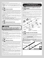
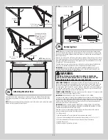
Working with a partner as needed, lift
the TorqueMaster
®
spring tube assembly up
and rest it on top of the flag angles.
Flag angle
Flag
angle
Center
bracket
Label
NOTE:
Cable drum assemblies are marked right and left hand. Cable drums and TorqueMas-
ter
®
spring tube assembly are cam shaped to fit together only one way.
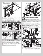
Starting on the right hand side, pre-wrap the cable drum with the counterbalance lift cable
1/2 wrap, as shown. Position the TorqueMaster
®
spring tube assembly so the cam peak
is pointing straight up. Slide the cable drum over the winding shaft until the cable drum
seats against the TorqueMaster
®
spring tube assembly. The winding shaft must extend past
the cable drum far enough to expose the splines and the grooves. Align the winding shaft
grooves with the round notch in the flag angle.
Right hand
cable drum
Right
hand
cable
drum
TorqueMaster
®
spring tube
assembly
Counterbalance
lift cable 1/2
wrap
Counterbalance
lift cable
Winding
shaft
Cam peak
straight up
Splines
Groove
Round notch
in flag angle
5”
Winding
shaft
Cam
peak
straight
up
Insert winding
shaft into flag
angle
Bearing
FOR DOUBLE SPRING APPLICATIONS:
Repeat for left hand side.
Left hand
cable drum
TorqueMaster
®
spring tube
assembly
Counterbalance lift
cable 1/2 wrap
Counterbalance
lift cable
Winding
shaft
5”
Left hand
cable drum
Splines
Groove
Round notch
in flag angle
Winding
shaft
Cam
peak
straight
up
Insert winding
shaft into flag
angle
Bearing
FOR SINGLE SPRING APPLICATIONS:
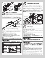
Insert the idler bracket into the left hand cable drum.
Lightly press the idler bracket into the cable drum until two distinct clicks are heard, or the
bracket is inserted all the way.
IMPORTANT:
ENSURE THE SNAPS ON THE IDLER BRACKET (LEFT HAND SIDE) ARE EN-
GAGED INTO THE LEFT HAND CABLE DRUM, SO THAT IT DOES NOT COME BACK OUT.
NOTE:
The idler bracket is designed for permanent assembly. Do not attempt to remove idler
bracket once inserted into the cable drum.
NOTE:
The idler bracket must extend past the cable drum far enough to expose the groove.
Align the idler bracket groove with the round notch in the flag angle.
Left hand
cable drum
TorqueMaster
®
spring tube
assembly
Counterbalance lift
cable 1/2 pre-wrap
Counterbalance
lift cable
Idler
bracket
Cam peak
straight up
Round
notch
Groove
Flag
angle
Snaps
Idler
bracket
Flag
angle
Bearing
Idler
bracket
Snaps
Groove
Left hand
cable drum
Idler
bracket
Snaps
Groove
Left
hand
cable
drum
Attaching End Brackets To Flag Angles
18
IMPORTANT:
WARNING TAGS MUST BE SECURELY ATTACHED TO END BRACKET(S).
IMPORTANT:
FOR SINGLE SPRING DOORS, ENSURE THE LEFT HAND CABLE DRUM BEARING
IS ALL THE WAY TO THE LEFT AND UP AGAINST THE FLAG ANGLE. IF THE CABLE DRUM IS
PULLED AWAY FROM THE FLAG ANGLE, THEN THE IDLER BRACKET CAN RUB AGAINST THE
CABLE DRUM CAUSING NOISE.
NOTE:
Drill 3/16” pilot holes into header for the lag screws.
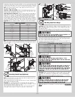
Beginning with the right hand side, slide the end bracket onto the winding shaft so that the
splines in the ratchet wheel fit onto the winding shaft grooves. Attach the end bracket to the
flag angle using (1) 5/16” - 18 x 3/4” carriage bolt, (1) 5/16” washer and (1) 5/16” - 18 hex
nut. Then secure the end bracket to the jamb using (1) 5/16” x 1-5/8” lag screw.
NOTE:
If ratchet wheel falls out of end bracket, refer to illustration for proper insertion
orientation.
FOR DOUBLE SPRING APPLICATIONS:
Repeat same process for left hand end bracket.
Grooves
Warning
tag
Disconnect cable
guide hole
Splines
Winding
shaft
Right
hand
end
bracket
Flag
angle
TorqueMaster
®
spring tube
assembly
Right hand
cable drum
Ratchet wheel
(oriented correctly)
FOR DOUBLE SPRING
APPLICATIONS:
Repeat
same process for left
hand end bracket.
5/16”
Washer
5/16”
Hex nut
Winding
shaft
5/16” -18 x 3/4”
Carriage bolt
TorqueMaster
®
spring tube
assembly
Right hand
cable drum
5/16” x 1-5/8”
Lag screw
Right
hand end
bracket
Flag
angle
Flag
angle
FOR SINGLE SPRING APPLICATIONS:
Secure the idler bracket to the flag angle using (1)
5/16” - 18 x 3/4” carriage bolt, (1) 5/16” washer and (1) 5/16” - 18 hex nut. Then secure
the idler bracket to the jamb using (1) 5/16” x 1-5/8” lag screw.
8


