INSTALLING CABLE DRUM ASSEMBLIES
14
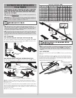
STEP 14 INSTRUCTIONS
14a.
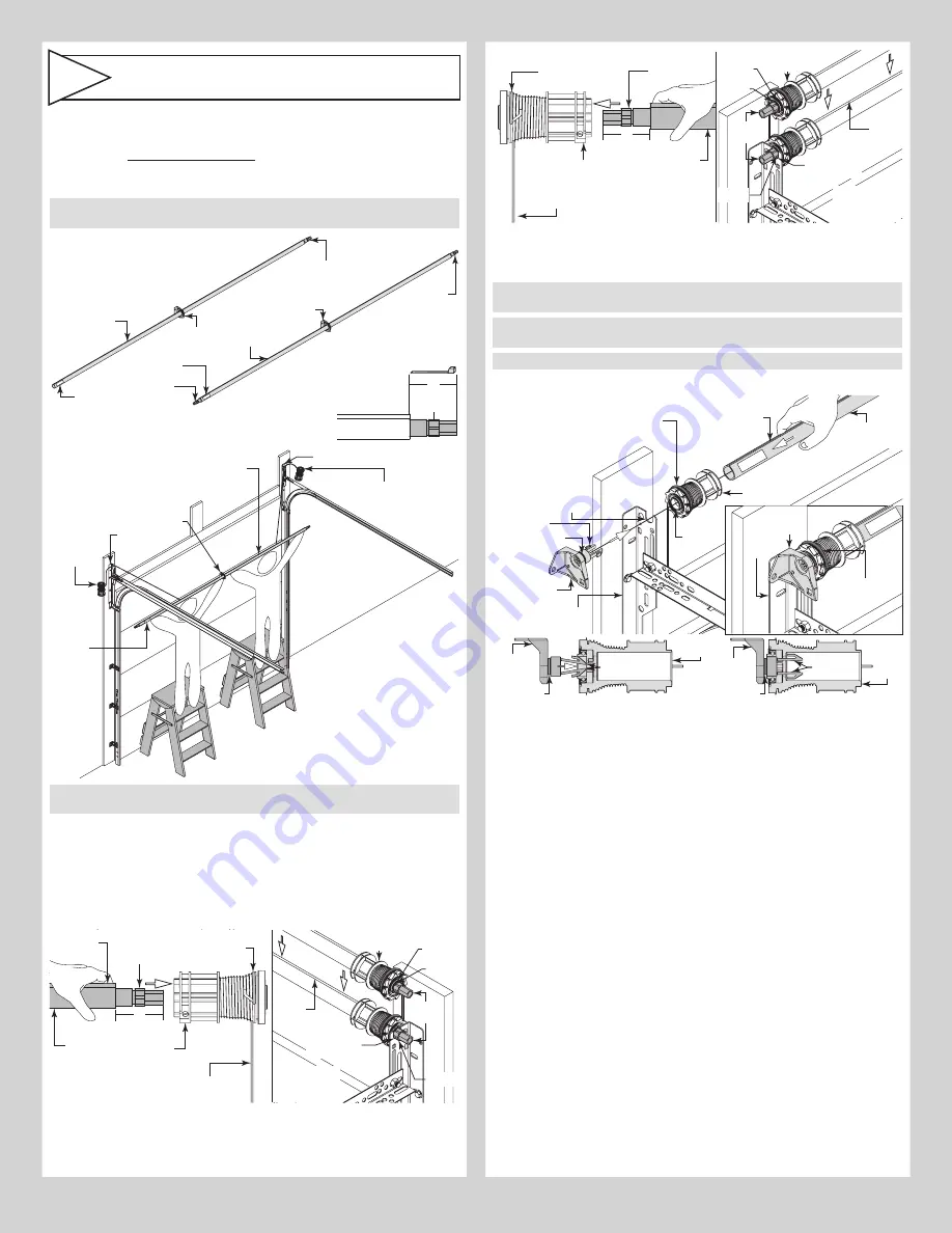
Shake the spring tube assembly
(I2.)
gently to extend the winding shafts out about 5”
on each side. For
single spring applications
, there will be no left hand spring in the spring
tube assembly.
14b.
Lift the spring tube assembly and rest it on top of the flag angles
(A1.)
.
NOTE:
Temporarily support the center of the spring tube assembly until the center bracket
(I1.)
is installed in Step 16 Attaching Center Bracket to Wall.
5”
Center
bracket
Winding
shaft
Winding
shaft
Winding
shaft
Winding
shaft
Spring tube
Center
bracket
Label
Label
Spring tube
(I2.)
Spring
tube
NOTE:
If winding shaft is not
visible out of the right hand side,
gently shake the spring tube
until winding shaft sticks out 5”.
NOTE:
If both winding shafts are not
visible, gently shake the spring tube
until both winding shaft sticks out 5”.
(I5.)
Left
hand cable
drum
assembly
(I5.)
Right hand
cable drum assembly
NOTE:
Working with a partner as needed, lift
the spring tube assembly up and rest it on
top of the flag angles.
(A1.)
Flag angle
(A1.)
Flag
angle
(I1.)
Center
bracket
Label
NOTE:
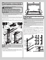
Cable drum assemblies are marked right and left hand. Cable drums and spring
tube assembly are cam shaped to fit together only one way.
14c.
Starting on the right hand side, pre-wrap the cable drum with the counterbalance lift
cable 1/2 wrap, as shown. Position the spring tube assembly so the cam peak is pointing
straight up.
14d.
Slide the cable drum over the winding shaft until the cable drum seats against the
spring tube assembly. The winding shaft must extend past the cable drum far enough to
expose the splines and the grooves. Align the winding shaft grooves with the round notch in
the flag angle.
Right hand
cable drum
Right
hand
cable
drum
Spring tube
assembly
Counterbalance
lift cable 1/2
wrap
Counterbalance
lift cable
Winding
shaft
Cam peak
straight up
Splines
Groove
Round notch
in flag angle
5”
Winding
shaft
Cam
peak
straight
up
Insert winding
shaft into flag
angle
Bearing
FOR DOUBLE SPRING APPLICATIONS:
Repeat for left hand side.
Left hand
cable drum
Spring tube
assembly
Counterbalance lift
cable 1/2 wrap
Counterbalance
lift cable
Winding
shaft
5”
Left hand
cable drum
Splines
Groove
Round notch
in flag angle
Winding
shaft
Cam
peak
straight
up
Insert winding
shaft into flag
angle
Bearing
FOR SINGLE SPRING APPLICATIONS:
14e.
Insert the idler bracket
(I6.)
into the left hand cable drum. Lightly press the idler bracket
into the cable drum until two distinct clicks are heard, or the bracket is inserted all the way.
IMPORTANT:
Ensure the snaps on the idler bracket (left hand side) are engaged into the
left hand cable drum, so that it does not come back out.
NOTE:
The idler bracket is designed for permanent assembly. Do not attempt to remove
idler bracket once inserted into the cable drum.
NOTE:
The idler bracket must extend past the cable drum far enough to expose the groove.
14f.
Align the idler bracket groove with the round notch in the flag angle.
Left hand
cable drum
Spring tube
assembly
Counterbalance lift
cable 1/2 pre-wrap
Counterbalance
lift cable
(I6.)
Idler
bracket
Cam peak
straight up
Round
notch
Groove
Flag
angle
Snaps
Idler
bracket
Flag
angle
Bearing
Idler
bracket
Snaps
Groove
Left hand
cable drum
Idler
bracket
Snaps
Groove
Left
hand
cable
drum
11


