33
November 2008
Part No. 920559 Rev H
3.17 Check the Audit Report Display Mode
(For Weights & Measures Officials
&
Service Purposes Only)
Verify that this mode can be accessed as per the instructions below.
On the computer the Weights and Measures audit trail is accessed by the use of a hand held remote. By entering
the Weights and Measure mode, one can view both the blend ratio audit trail and volume metering unit change
counter required by Weights and Measures.
The Weights and Measures mode is side specific, therefore, it shows the blend ratio logs and volume metering
unit logs for the side that your are facing.
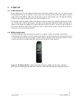
Entering this mode is via a hand held remote. Remotes are available at the station. Both the audit trail data and
gallons to liters conversion data is obtained by the use of the hand held remote. To use the remote, point at the
sales display near the center of the area where the Totals and Volume values are displayed. Keep the remote
within 12 inches of the main sales display for proper operation.
To enter the Weights and Measures mode perform the following:
1. Press
Enter
and then press
Clear
twice.
If you do not press another button in 20 seconds, the computer will step through the values with-
out interaction from the remote.
2. The sales display will show
bLEnd rAtioS
and the current blend ratios for all blended products.
3. Press
NEXT
to view the Blend Ratio Change Counter mode
4. Press
NEXT
will allow you to toggle through each blend ratio change counter and pressing
NEXT
button again will enter into the View Volume Metering Unit Change Counters mode.
5. The sale display will show
n
, where
n
equals the Unit Change Event Number.
6. The volume display contains the metering unit that it was changed to with the following descrip-
tion:
LitErs
Liters volume unit
US GAL
U.S. Gallons volume unit
IP GAL
Imperial Gallons volume unit
7. Press
CLEAR
and then
ENTER
three times to go out of the Weights and Measures mode.
3.18 IDPOS Dispensers
See the latest version of IDPOS Support CD for additional startup procedures on IDPOS dispensers.
3.19 iX
™
CAT Dispensers and iX CAT Address
For iX CAT dispensers, perform the iX CAT self-test procedure in Appendix A2 of this manual. The procedure
includes setting the CAT ID address. The CAT address is normally set to the same address as the pump fueling
point address for that side of the dispenser. Some customers may require additional startup procedures for iX
CAT dispensers. If necessary, refer to the iX CAT Software Installation manual, part number 920880.
3.20 Bill Acceptor Operation
For dispensers equipped with the Bill Acceptor (BAC), check the operation of the BAC and screen prompts by
simply inserting bills and checking that the dispenser will dispense product accordingly. To retrieve the money,
as shown in the following photos, unlock the bill acceptor front door, unlock the cash cassette (turn key to left),
remove cassette, and remove the inserted bills from the cassette. Reinsert the cassette and lock doors. Verify
that receipt printed when cassette was removed and check that money totals on the receipt correspond to the
bills inserted.
Note:
On standard Ovation dispensers, locate the
BAM board
inside the service door and
set
switch SW2 address to the CAT address
, which is normally the fueling point ID. See the photo and table on
the very last page in this manual for the switch settings. Also note that this step is not performed on iX CAT
model dispensers.
Summary of Contents for Ovation
Page 1: ...INSTALLATION Ovation Dispensers OPERATION...
Page 3: ...November 2008 Part No 920559 Rev H Ovation Series Dispensers Installation Operation...
Page 4: ...November 2008 Part No 920559 Rev H...
Page 54: ...48 Part No 920559 Rev H November 2008...
Page 66: ...60 Part No 920559 Rev H November 2008...
Page 67: ...61 November 2008 Part No 920559 Rev H DISTANCE BETWEEN EYE BOLTS 33 1...
Page 68: ...62 Part No 920559 Rev H November 2008 INSTALLATION INSTRUCTION page 1 of 2 OVATION MODEL R13...
Page 69: ...63 November 2008 Part No 920559 Rev H INSTALLATION INSTRUCTION page 2 of 2 OVATION MODEL R13...
Page 70: ...64 Part No 920559 Rev H November 2008 INSTALLATION INSTRUCTION page 1 of 2 OVATION MODEL B23...
Page 71: ...65 November 2008 Part No 920559 Rev H INSTALLATION INSTRUCTION page 2 of 2 OVATION MODEL B23...
Page 74: ...68 Part No 920559 Rev H November 2008 INSTALLATION INSTRUCTION page 1 of 2 OVATION MODEL R11...
Page 75: ...69 November 2008 Part No 920559 Rev H INSTALLATION INSTRUCTION page 2 of 2 OVATION MODEL R11...
Page 76: ...70 November 2008 Part No 920559 Rev H...
Page 77: ...71 November 2008 Part No 920559 Rev H 2 7151 C TYPICAL SITE WIRING...
Page 78: ...72 Part No 920559 Rev H November 2008...
Page 80: ...74 Part No 920559 Rev H November 2008...
Page 81: ...75 November 2008 Part No 920559 Rev H APPENDIX D SITE INTERCONNECTION DIAGRAMS...
Page 82: ...76 Part No 920559 Rev H November 2008 Figure D 1 Backroom Installation Wayne Control System...
Page 84: ...78 Part No 920559 Rev H November 2008 Figure D 3 Pump Relay Installation Wiring Diagram...

