background image

2

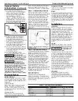
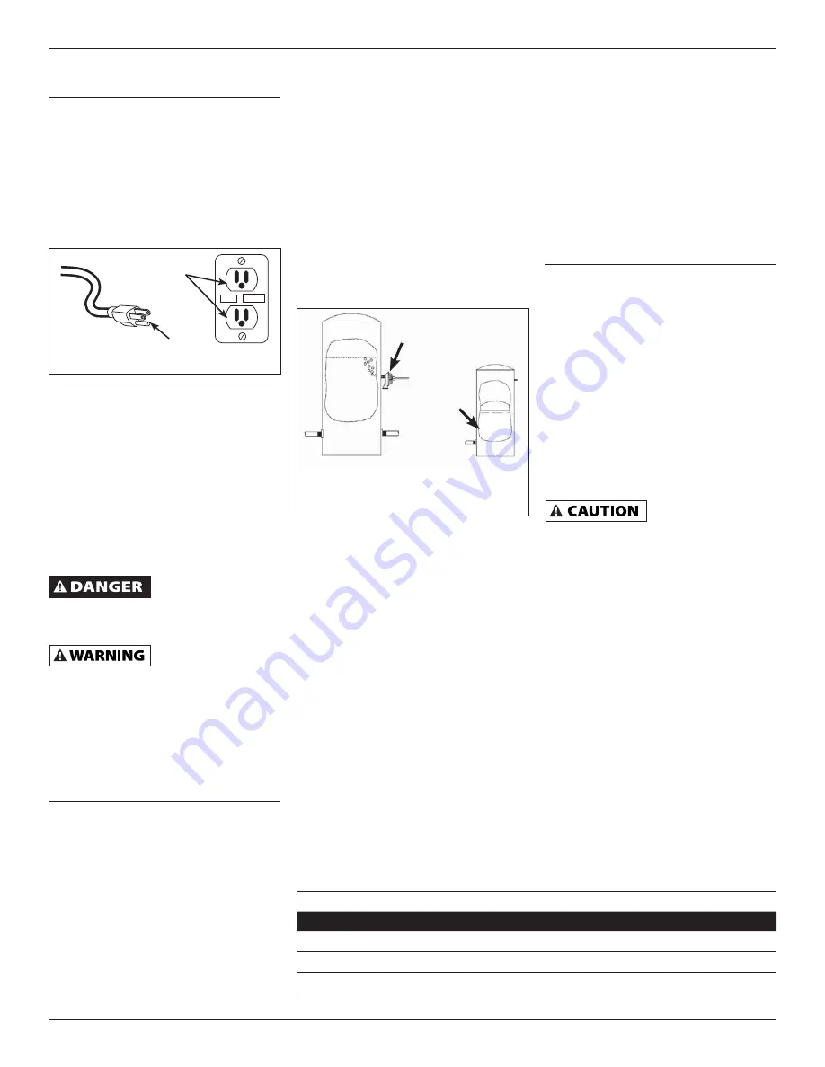
19. To reduce the risk of electrical 

shock, the pump should be plugged 
directly into a properly installed 
and grounded 3-prong grounding 
type receptacle, as shown in 
Figure 1.  The green (or green and 
yellow) conductor in the cord is the 
grounding wire.  The motor must be 
securely and adequately grounded 
for protection against shock.

20. Where a 2-prong is encountered, 

replace the plug with a properly 
grounded 3-prong receptacle in 
accordance with the National Electrical 
Code, local codes and ordinances.  
To ensure a proper ground, the 
grounding means must be tested by a 
licensed or certified electrician.

21. Use only 3-wire extension cords that 

have a 3-prong, grounding type plug, 
and 3-pole receptacles that accept 
the equipment plug.

22. Use wire of adequate size to 

minimize voltage drop at the motor.


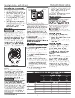
Do not handle

  pump or pump motor 

with wet hands, when standing on a wet 
or damp surface or when standing in 
water.  Fatal electrical shock could occur.


Pump motor is

  equipped with an 

automatic resetting thermal protector 
and may restart unexpectedly.  Protector 
tripping is an indication of motor 
overloading because of operating pump 
at low heads (low discharge restriction), 
excessively high or low voltage, 
inadequate wiring, incorrect motor 
connections or defective motor or pump.

Pre-Installation

WATER SUPPLIES

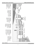
The water supplies illustrated in Figure 
13 are possible sources for water.  These 
water supplies can be divided into two 
categories:

SURFACE WATER
Water from a lake, stream, pond and 
cistern.  This water is usually not fi t 
for human consumption, but may be 
suitable for washing, irrigation or other 
household uses.

GROUND WATER
Water found in the water bearing 
stratum at various levels beneath the 

General Safety 
Information 

(Continued)

earth.  Of all the fresh water found on 
earth only 3 percent is found on the 
surface and 97 percent is underground.

TANKS - CONVENTIONAL STORAGE

The function of the tank is to store a 
quantity of water under pressure.  When 
full, the tank contains approximately 
2/3 water and 1/3 compressed air.  The 
compressed air forces the water out 
of the tank when a faucet is opened.  
An air volume control automatically 
replaces air lost or absorbed into the 
water.  The usable water, or drawdown 
capacity, of the tank is approximately 
1/6 of the tanks total volume when 
operated on a “20-40” pressure setting 
(Figure 2).

TANKS - PRECHARGED STORAGE

A precharged storage tank has a fl exible 
bladder or diaphragm that acts as a 
barrier between the compressed air 
and water.  This barrier prevents the 
air from being absorbed into the water 
and allows the water to be acted on by 
compressed air at initially higher than 
atmospheric pressures (precharged).  
More usable water is provided than with 
a conventional type tank.  Precharged 
tanks are specifi ed in terms of a 
conventional tank.  For example, a 20 
gallon precharged tank will have the same 
usable water or drawdown capacity as a 
40 gallon conventional tank, but the tank 
is smaller in size (Figure 2).

PRESSURE SWITCH

The pressure switch provides for 
automatic operation.  The pump starts 
when pressure drops to a cut-in setting. 
The pump stops when pressure reaches a 
cut-out setting.

TEST

RESET

Grounded Pin

Grounded 
Outlet

Figure 1

PACKAGE SYSTEMS

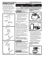
There are four jet pump/tank assemblies 
sold as packages (Chart 1).

WELLS

A new well should be pumped clear of 
sand before installing the pump.  Sand 
will damage the pumping parts and seal.  
The draw-down level of the well should 
not exceed the maximum rated depth 
for the pump.  The capacity of the pump 
will be reduced and a loss of prime may 
occur.

Installation

LOCATION

Select a location as close to the water 
supply as possible.  Be sure to comply 
with any state or local codes regarding 
the placement of the pump.  The 
equipment must be protected from the 
elements.  A basement or heated pump 
house is a good location.  Make sure 
the pump has proper ventilation.  The 
temperature surrounding the pump is 
not to exceed 100° F (40°C) or nuisance 
tripping of the motor overload may 
occur.

PIPING

Piping may be copper, steel, rigid PVC 
plastic or fl exible polyethylene plastic.


Flexible pipe is not

 recommended on 

suction pipe (inlet pipe).

The pipe must be clean and free of rust 
or scale.  Use a pipe joint compound 
on the male threads of the metal pipe.  
Tefl on® tape should be used with plastic 
threads.  All connections must be air 
tight to insure normal operation.

Slope all inlet piping upwards towards 
the pump to prevent trapping air.  
Unions or hose couplings can be 
installed near pump to facilitate removal 
for servicing or storage.  A rubber hose 
installed between the water system and 
the house piping will reduce the noise 
transmitted to the house.

PIPE SIZES

Long horizontal pipe runs and an 
abundance of fi ttings and couplers 
decrease water pressure due to friction 
loss. See Chart 2 to determine the proper 
pipe size. 

www.waynepumps.com

Operating Instructions and Parts Manual


Shallow Well Model Systems

Figure 2 - Conventional & Precharged 
Storage Tanks

Precharged 

Tank

Conventional 

Tank

Bladder

Air Volume Control

CHART 1 - JET PUMP/ TANK ASSEMBLIES

Type

Air Volume Congrol Required

Well X

Precharged

No

PCA

Precharged

No

12P & 30P

Conventional

Yes

FX Horizontal

Precharged

No

Summary of Contents for Shallow well model

Page 1: ...ure 6 Periodically inspect pump and system components Perform routine maintenance as required See Maintenance 7 Personal Safety a Wear safety glasses at all times when working with pumps b Keep work a...

Page 2: ...r This barrier prevents the air from being absorbed into the water and allows the water to be acted on by compressed air at initially higher than atmospheric pressures precharged More usable water is...

Page 3: ...oints or couplings will allow air to leak into the pipe and cause abnormal pump operation Make sure to use pipe joint compound on all male pipe threads DUG WELL CISTERN LAKE AND SPRING INSTALLATION FI...

Page 4: ...ny maintenance Operation PRIMING THE SHALLOW WELL PUMP To prevent damage to the pump do not start motor until pump has been filled with water 1 Remove prime plug Figure 4 or 5 2 Fill pump and piping c...

Page 5: ...from impeller hub and seal plate INSTALLING NEW SHAFT SEAL Before handling shaft seal parts wipe hands clean Dirt or grease can damage the seal 1 Wet the inside of the seal cavity on seal plate and th...

Page 6: ...6 Operating Instructions and Parts Manual Shallow Well Model Systems www waynepumps com Notes...

Page 7: ...7 Operating Instructions and Parts Manual Shallow Well Model Systems Notes www waynepumps com...

Page 8: ...8 Operating Instructions and Parts Manual Shallow Well Model Systems www waynepumps com Notes...

Page 9: ...well 7 Air volume control diaphragm ruptured 8 Foot valve may be clogged or stuck closed 9 Pump not fully primed 10 Control valve completely closed deep well 11 Water level below maximum lift specific...

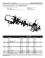
Page 10: ...assembly 56393 56393 56393 1 6 Impeller 23285 021 23285 022 23285 022 1 7 Diffuser 17148 021 17148 021 17148 021 1 8 Screw 67007 001 67007 001 67007 001 2 9 O ring 15557 15557 15557 1 10 Venturi 1715...

Page 11: ...concrete to prevent cave in D DRIVEN WELL Pipe with a pointed screen is driven into the ground below the water table The depth is usually less than 50 feet Available diameters are 1 through 2 E DRILL...

Page 12: ...AGES OR EXPENSES WHATSOEVER IS EXCLUDED Some states do not allow limitations on how long an implied warranty lasts or do not allow the exclusions or limitations of incidental or consequential damages...

Page 13: ...d essayer de monter de d placer ou de proc der au service ou l entretien Verouiller le sectionneur de puissance dans la position ouverte tiquetter le sectionneur de puissance afin d viter l alimentat...

Page 14: ...de d charge basse tension tr s lev e ou basse installation de fils incorrecte branchements de moteur incorrects ou moteur pompe d fectueux Pr Installation SOURCES D EAU Les sources d eau possibles so...

Page 15: ...mpe pour puits de surface si la pompe est situ e moins de 7 62 m verticalement du niveau d eau Les pompes pour puits de surface ont un seul tuyau entre la pompe et la source d eau Figure 3 PUITS FOR F...

Page 16: ...La tension de la source d alimentation doit correspondre avec la tension de la pompe Toutes les pompes de puits de surface sauf le mod le SWS50BOOST ont des moteurs tension double pr r gl s en usine 1...

Page 17: ...le plus bas du syst me pour dissiper toute l eau pressuris e dans le syst me 3 Amorcer la pompe Amor age De Pompes Pour Puits De Surface 4 Brancher nouveau l alimentation la pompe REMARQUE Lors du rem...

Page 18: ...assure le vidange et l amor age correct 3 Positionner la pi ce du joint d arbre rotative sur la turbine et appuyer soigneusement afin de ne pas appuyer sur la surface polie du joint 4 Positionner la t...

Page 19: ...effonde D PUITS ENFONC Un tuyau avec un tamis pointu est enfonc dans la terre sous le niveau hydrostatique La profondeur est g n ralement moins de 15 m Les diam tres disponibles sont 2 5 cm 5 1 cm E P...

Page 20: ...anneau carr 17150 001 1 5 Assemblage de bo te d tanch it 56393 1 6 Rotor 23285 002 1 7 Diffuseur 17148 001 1 8 Vis 67007 001 9 Joint torique 15557 1 10 Venturi 17151 002 1 11 Buse 15672 1 12 Bouchon...

Page 21: ...aisser la circulation aller retour de la pompe b Purger l air enferm dans la pompe normalement cause d une vanne ferm e dans la plomberie de d charge 2 Filtre en ligne r duit la circulation 2 V rifier...

Page 22: ...dur e pour les garanties implicites ni l exclusion ni la limite des dommages fortuits ou indirects Les limites pr c dentes peuvent donc ne pas s appliquer Cette garantie limit e donne l acheteur des...

Page 23: ...s materiales 5 Antes de cada uso inspeccione las mangueras para cerciorarse de que no est n d biles ni gastadas Aseg rese de que todas las conexiones est n seguras 6 Inspeccione peri dicamente la bomb...

Page 24: ...cisterna Esta agua habitualmente no es adecuada para consumo humano pero podr a usarse para lavar irrigar u otros usos dom sticos AGUAS SUBTERR NEAS El agua que se encuentra en los diversos estratos p...

Page 25: ...vula de aspiraci n debe estar por lo menos a 45 cm 18 pulg del fondo del pozo de no ser as podr a aspirar arena o sedimento dentro del sistema 4 Despu s que se haya alcanzado la profundidad adecuada i...

Page 26: ...i n sobre superficie excepto la SWS50BOOST tienen motores de doble voltaje preconfigurados en la f brica a 115 voltios Para conectarlas a circuitos de 230 voltios simplemente gire la perilla al voltaj...

Page 27: ...ebe haber agua en la cubierta en espiral de la bomba voluta cuando este funcionando para evitar danos internos en las piezas de sellado Vea las secciones sobre cebado de pozos poco profundos o de pozo...

Page 28: ...alineadas con las leng etas del armaz n del motor Figura 11 Esta ubicaci n se debe hacer para asegurar un drenaje y cebado adecuados 3 Sit e la pieza rotatoria del sello del eje en el impulsor y pres...

Page 29: ...el flujo hacia y desde la bomba b Deje salir el aire atrapado en la bomba normalmente debido a una v lvula cerrada en la tuber a de salida 2 El filtro en l nea est restringiendo el flujo 2 Verifique...

Page 30: ...A No de Ref Descripci n No Repuestos Cte 1 Motor 32059 001 1 2 Tornillo 16636 002 3 Plato de cierre 17145 001 1 4 Junta cuadrada de goma del anillo 17150 001 1 5 Ensamblaje de sellado del eje 56393 1...

Page 31: ...POZO ACCIONADO Se acciona una tuber a con una pantalla con punta en la tierra por debajo de la capa fre tica La profundidad por lo general es menor a 15 25 m 50 pies Los di metros comunes fluct an ent...

Page 32: ...XCLUIDOS Algunos estados no permiten que se establezcan l mites en la duraci n de las garant as implicitas o no permiten que se excluyan ni se establezcan l mites en los da os por incidentes o consecu...

Reviews: