background image

4

Operating Instructions and Parts Manual


Shallow Well Model Systems

1.  Shut off the power to the pump.
2.  Open the faucet nearest the tank and 

allow all water to drain from the tank.

3.  Measure the tank precharge at the 

valve stem using a tire pressure gauge.

4.  If necessary, precharge with an air 

pump to 28 - 30 psi on 1/2, 3/4 and 1 
HP pumps.

5.  Slope the horizontal pipes upward 

toward the pump to prevent trapping 
air.  If the horizontal distance 
exceeds 25 feet, see Chart 2 for the 
recommended pipe size.

Electrical


Risk of electrical

  shock.  This pump is 

designed for indoor installation only.

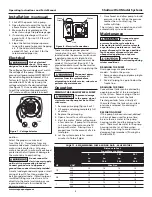
The voltage of power supply must match 
the voltage of the pump. All above 
ground well pumps except SWS50BOOST 
have dual voltage motors preset at the 
factory to 115 volts. The motors can be 
converted to 230 volts by turning the 
voltage selector to the desired voltage 
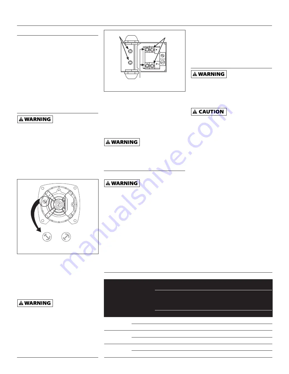
(See Figure 7).  Use a needle nose pliers 
to pull the selector out approximately 
1/4”, rotate and then reinsert in correct 

position. 

Select the proper size wire and 
fuse (Chart 3).  Time delay fuses are 
recommended over standard fuses for 
motor circuit protection.  All pump 
motors have built-in automatic overload 
protection that will prevent damage to 
the motor due to overheating.


Do not connect to

  electric power supply 

until unit is permanently grounded.  
Connect ground wire to approved 
ground then connect terminal provided.

A metal underground water pipe or well 
casing at least 10 feet long makes the 
best ground electrode.  If plastic pipe or 
insulated fi ttings are used, run a wire 
directly to the metal well casing or use 
a ground electrode furnished by the 
power company.

There is only one proper ground 
terminal on the unit.  The terminal(s) is 
located under the pressure switch cover, 
is painted green and is identifi ed as 
GRD.  The ground connection must be 
made at this terminal (Figure 8).  The 
ground conductor must not be smaller 
than the circuit conductors supplying the 
motor.

 Disconnect 

power

  and release all 

pressure from the system before 
attempting to install, service, relocate or 
perform any maintenance.

Operation

PRIMING THE SHALLOW WELL PUMP


To prevent damage

  to the pump, do not 

start motor until pump has been fi lled 
with water.

1.  Remove prime plug (Figure 4 or 5).
2.  Fill pump and piping completely full 

of water.

3.  Replace the prime plug.
4.  Open a faucet to vent the system.
5.  Start the motor.  Water will pump in 

a few minutes.  If pump fails to prime 
in 5 minutes, stop motor and refill 
pump with water.  Priming time is 
proportional to the amount of air in 
inlet pipe.

6.  Let the system operate for several 

minutes to flush all pipes.

7.  Close faucet and allow pump to build 

pressure in tank.  When the pressure 
reaches the cut-out setting, the 
motor will stop.

The system is now in operation and will 
automatically cycle on demand.

Maintenance

 Disconnect 

power

  and release all 

pressure from the system before 
attempting to install, service, relocate 
or perform any maintenance.  Lock the 
power disconnect in the open position.  
Tag the power disconnect to prevent 
unexpected application of power.


Protect the pump

  from freezing during 

winter conditions.

DRAINING THE PUMP

Drain openings are provided on all 
models.  To drain the pump:

1.  Remove drain plug and prime plug to 

vent the system.

2.  Drain all piping to a point below the 

freeze line.

DRAINING THE TANK

Conventional tanks can be drained by 
opening an outlet at the lowest point 
in the system.  Remove plug or the air 
volume control to vent the tank.

Precharged tanks force virtually all 
the water from the tank when system 
pressure is released.  No draining is 
necessary.

RESTARTING PUMP

If the pump has been serviced, drained 
or has not been used for some time, 
be sure there is water in the pump 
housing (volute) and the piping to the 
well.  There must be water in the pump 
housing (volute) at all times when 
the pump is running to avoid internal 
damage of seal members (Priming the 
Shallow Well).

www.waynepumps.com

115 V

230 V

115 V

230 V

Figure 7 - Voltage Selector

L2

3

L1

1

Figure 8 - Electrical Connections

Line

Motor

Ground 
Screw

CHART 3 - RECOMMENDED FUSE & WIRING DATA - 60 HZ MOTORS

HP

VOLT

Distance in Feet

From Meter to Motor

0

51

101

201

to

to

to

to

50

100

200

300

Wire Size

1/2

115

15

14

14

10

230

10

14

14

14

3/4

115

15

14

14

8

230

10

14

14

14

1

115

20

12

12

8

230

10

14

14

14

Installation


(Continued)

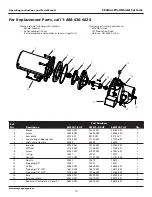
Summary of Contents for Shallow well model

Page 1: ...ure 6 Periodically inspect pump and system components Perform routine maintenance as required See Maintenance 7 Personal Safety a Wear safety glasses at all times when working with pumps b Keep work a...

Page 2: ...r This barrier prevents the air from being absorbed into the water and allows the water to be acted on by compressed air at initially higher than atmospheric pressures precharged More usable water is...

Page 3: ...oints or couplings will allow air to leak into the pipe and cause abnormal pump operation Make sure to use pipe joint compound on all male pipe threads DUG WELL CISTERN LAKE AND SPRING INSTALLATION FI...

Page 4: ...ny maintenance Operation PRIMING THE SHALLOW WELL PUMP To prevent damage to the pump do not start motor until pump has been filled with water 1 Remove prime plug Figure 4 or 5 2 Fill pump and piping c...

Page 5: ...from impeller hub and seal plate INSTALLING NEW SHAFT SEAL Before handling shaft seal parts wipe hands clean Dirt or grease can damage the seal 1 Wet the inside of the seal cavity on seal plate and th...

Page 6: ...6 Operating Instructions and Parts Manual Shallow Well Model Systems www waynepumps com Notes...

Page 7: ...7 Operating Instructions and Parts Manual Shallow Well Model Systems Notes www waynepumps com...

Page 8: ...8 Operating Instructions and Parts Manual Shallow Well Model Systems www waynepumps com Notes...

Page 9: ...well 7 Air volume control diaphragm ruptured 8 Foot valve may be clogged or stuck closed 9 Pump not fully primed 10 Control valve completely closed deep well 11 Water level below maximum lift specific...

Page 10: ...assembly 56393 56393 56393 1 6 Impeller 23285 021 23285 022 23285 022 1 7 Diffuser 17148 021 17148 021 17148 021 1 8 Screw 67007 001 67007 001 67007 001 2 9 O ring 15557 15557 15557 1 10 Venturi 1715...

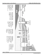
Page 11: ...concrete to prevent cave in D DRIVEN WELL Pipe with a pointed screen is driven into the ground below the water table The depth is usually less than 50 feet Available diameters are 1 through 2 E DRILL...

Page 12: ...AGES OR EXPENSES WHATSOEVER IS EXCLUDED Some states do not allow limitations on how long an implied warranty lasts or do not allow the exclusions or limitations of incidental or consequential damages...

Page 13: ...d essayer de monter de d placer ou de proc der au service ou l entretien Verouiller le sectionneur de puissance dans la position ouverte tiquetter le sectionneur de puissance afin d viter l alimentat...

Page 14: ...de d charge basse tension tr s lev e ou basse installation de fils incorrecte branchements de moteur incorrects ou moteur pompe d fectueux Pr Installation SOURCES D EAU Les sources d eau possibles so...

Page 15: ...mpe pour puits de surface si la pompe est situ e moins de 7 62 m verticalement du niveau d eau Les pompes pour puits de surface ont un seul tuyau entre la pompe et la source d eau Figure 3 PUITS FOR F...

Page 16: ...La tension de la source d alimentation doit correspondre avec la tension de la pompe Toutes les pompes de puits de surface sauf le mod le SWS50BOOST ont des moteurs tension double pr r gl s en usine 1...

Page 17: ...le plus bas du syst me pour dissiper toute l eau pressuris e dans le syst me 3 Amorcer la pompe Amor age De Pompes Pour Puits De Surface 4 Brancher nouveau l alimentation la pompe REMARQUE Lors du rem...

Page 18: ...assure le vidange et l amor age correct 3 Positionner la pi ce du joint d arbre rotative sur la turbine et appuyer soigneusement afin de ne pas appuyer sur la surface polie du joint 4 Positionner la t...

Page 19: ...effonde D PUITS ENFONC Un tuyau avec un tamis pointu est enfonc dans la terre sous le niveau hydrostatique La profondeur est g n ralement moins de 15 m Les diam tres disponibles sont 2 5 cm 5 1 cm E P...

Page 20: ...anneau carr 17150 001 1 5 Assemblage de bo te d tanch it 56393 1 6 Rotor 23285 002 1 7 Diffuseur 17148 001 1 8 Vis 67007 001 9 Joint torique 15557 1 10 Venturi 17151 002 1 11 Buse 15672 1 12 Bouchon...

Page 21: ...aisser la circulation aller retour de la pompe b Purger l air enferm dans la pompe normalement cause d une vanne ferm e dans la plomberie de d charge 2 Filtre en ligne r duit la circulation 2 V rifier...

Page 22: ...dur e pour les garanties implicites ni l exclusion ni la limite des dommages fortuits ou indirects Les limites pr c dentes peuvent donc ne pas s appliquer Cette garantie limit e donne l acheteur des...

Page 23: ...s materiales 5 Antes de cada uso inspeccione las mangueras para cerciorarse de que no est n d biles ni gastadas Aseg rese de que todas las conexiones est n seguras 6 Inspeccione peri dicamente la bomb...

Page 24: ...cisterna Esta agua habitualmente no es adecuada para consumo humano pero podr a usarse para lavar irrigar u otros usos dom sticos AGUAS SUBTERR NEAS El agua que se encuentra en los diversos estratos p...

Page 25: ...vula de aspiraci n debe estar por lo menos a 45 cm 18 pulg del fondo del pozo de no ser as podr a aspirar arena o sedimento dentro del sistema 4 Despu s que se haya alcanzado la profundidad adecuada i...

Page 26: ...i n sobre superficie excepto la SWS50BOOST tienen motores de doble voltaje preconfigurados en la f brica a 115 voltios Para conectarlas a circuitos de 230 voltios simplemente gire la perilla al voltaj...

Page 27: ...ebe haber agua en la cubierta en espiral de la bomba voluta cuando este funcionando para evitar danos internos en las piezas de sellado Vea las secciones sobre cebado de pozos poco profundos o de pozo...

Page 28: ...alineadas con las leng etas del armaz n del motor Figura 11 Esta ubicaci n se debe hacer para asegurar un drenaje y cebado adecuados 3 Sit e la pieza rotatoria del sello del eje en el impulsor y pres...

Page 29: ...el flujo hacia y desde la bomba b Deje salir el aire atrapado en la bomba normalmente debido a una v lvula cerrada en la tuber a de salida 2 El filtro en l nea est restringiendo el flujo 2 Verifique...

Page 30: ...A No de Ref Descripci n No Repuestos Cte 1 Motor 32059 001 1 2 Tornillo 16636 002 3 Plato de cierre 17145 001 1 4 Junta cuadrada de goma del anillo 17150 001 1 5 Ensamblaje de sellado del eje 56393 1...

Page 31: ...POZO ACCIONADO Se acciona una tuber a con una pantalla con punta en la tierra por debajo de la capa fre tica La profundidad por lo general es menor a 15 25 m 50 pies Los di metros comunes fluct an ent...

Page 32: ...XCLUIDOS Algunos estados no permiten que se establezcan l mites en la duraci n de las garant as implicitas o no permiten que se excluyan ni se establezcan l mites en los da os por incidentes o consecu...

Reviews: