43
November 1992
Part No. 917543 Rev. A
5.4.
BLEND VALVE
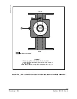
The blend valve is used in blending dispensers to mix two different grades of product in
order to produce intermediate grades which have an octane rating somewhere between
the first two. The blend valve is designed in such a way that as it restricts the flow of one
product it permits increased flow of the other.
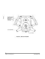
In order to accomplish this the valve has two separate chambers. Each of these chambers
has its own inlet and outlet. The outlets come together at some point after the blend valve
and this point is where the mixing actually takes place. Each of the outlets is covered, in
some part, by a “shoe”. These “shoes” are attached to a drive shaft in such a way that as
one port is being uncovered the other is being covered, thus adjusting the flow of each
product. (see Figure 5-9.)
5.5.
COMPACT PUMPING UNIT
The Wayne compact pumping unit is a rotary-type gear pump. These pumps are called
“self-priming” because they will remove all air and vapor from the suction line without
assistance from an outside source. Rotary pumps operate with extremely close clearances
between the rotating member and the pump casing. This feature enables them to be good
“self-primers” and ideal pumps for gasoline dispensing systems.
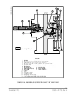
The bypass valve in the compact pumping unit should be set at one of two pressures. If
the pumping unit is driven by a 1/3 horsepower motor the pressure should be 21-22 psi.
If the motor is 3/4 horsepower the bypass pressure should be 28-30 psi. To adjust the
bypass pressure remove the acorn nut on the bypass assembly, then loosen the locking nut
on the adjusting screw. Tightening the adjusting screw will raise the pressure; loosening
the screw will lower the pressure.
Also part of the compact pumping unit is the air eliminator. This is a fairly large holding
chamber with an outlet at the top. This outlet is attached to the sump assembly. As
product is delivered to the air eliminator the vapor, in the form of foam, rises to the top
and passes through the outlet to the sump assembly.
5.5.1.
Priming the Compact Pumping Unit
It is not advisable to run any type of pumping unit dry during the priming
process, therefore, it is recommended that a small quantity (1/2 pint or 1/4
liter) of motor oil be inserted through the priming port of the pumping unit
before commencing operation.
If difficulty is encountered using the priming port, the pumping unit should be
primed by removing the pressure relief valve seal cap complete with adjusting
screw, the valve spring and the valve poppet (for more detailed information on
the service and troubleshooting of the compact pumping unit see The Wayne
Compact Pumping Unit—Service; part number 917466)
Summary of Contents for Vista Series
Page 1: ...SERVICE Vista Blending and Non blending Suction Pumps and Remote Dispensers...
Page 4: ...Part No 917543 Rev A November 1992...
Page 12: ...x Part No 917543 Rev A November 1992...
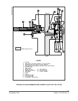
Page 34: ...22 Part No 917543 Rev A November 1992 FIGURE 4 1 NOZZLE BOOT ASSEMBLY WITH MICRO SWITCH...
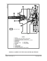
Page 35: ...23 November 1992 Part No 917543 Rev A FIGURE 4 2 NOZZLE BOOT ASSEMBLY WITH TILT SWITCH...
Page 36: ...24 Part No 917543 Rev A November 1992...
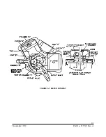
Page 53: ...41 November 1992 Part No 917543 Rev A FIGURE 5 7 METER CUTAWAY...
Page 54: ...42 Part No 917543 Rev A November 1992 FIGURE 5 8 METER ADJUSTMENT...
Page 58: ...46 Part No 917543 Rev A November 1992...
Page 69: ...57 November 1992 Part No 917543 Rev A FIGURE 7 1 REPLACING THE DUPLEX II COMPUTER...
Page 71: ...59 November 1992 Part No 917543 Rev A FIGURE 7 2 REPLACING THE INTRINSIC SAFE BARRIER BOARD...
Page 72: ...60 Part No 917543 Rev A November 1992 FIGURE 7 3 REPLACING THE INTEGRATED DISPLAY BOARD...
Page 75: ...63 November 1992 Part No 917543 Rev A FIGURE 7 5 REPLACING THE SOLENOID DRIVE BOARD...
Page 82: ...70 Part No 917543 Rev A November 1992...
Page 84: ...72 Part No 917543 Rev A November 1992...
Page 106: ...94 Part No 917543 Rev A November 1992...
Page 110: ...98 Part No 917543 Rev A November 1992 FIGURE B 4 THE DEM IN THE SERVICE POSITION...
Page 112: ...100 Part No 917543 Rev A November 1992 FIGURE B 6 DUPLEX II COMPUTERS J3 CONNECTOR PINOUT...
Page 114: ...102 Part No 917543 Rev A November 1992 FIGURE B 8 DUPLEX II COMPUTERS J11 CONNECTOR PINOUT...
Page 115: ...103 November 1992 Part No 917543 Rev A FIGURE B 9 DUPLEX II COMPUTERS J6 CONNECTOR PINOUT...
Page 116: ...104 Part No 917543 Rev A November 1992 FIGURE B 10 DUPLEX II COMUTERS J1 CONNECTOR PINOUT...
Page 125: ...113 November 1992 Part No 917543 Rev A FIGURE B 18B 4 PRODUCT SOLENOID DRIVE BOARD...
Page 126: ...114 Part No 917543 Rev A November 1992 FIGURE B 18C BLENDER SOLENOID DRIVE BOARD...
Page 133: ...121 November 1992 Part No 917543 Rev A FIGURE B 24 MANUALLY TURNING THE PHOTOCOUPLER...
Page 139: ...127 November 1992 Part No 917543 Rev A FIGURE B 29 LIGHTED CASH CREDIT INTERFACE BOARD...
Page 144: ...132 Part No 917543 Rev A November 1992...
Page 145: ...133 November 1992 Part No 917543 Rev A APPENDIX C DISPENSER INTERNAL WIRING DIAGRAMS...
Page 146: ...134 Part No 917543 Rev A November 1992...
Page 150: ...138 Part No 917543 Rev A November 1992 1 6560 D INTERNAL WIRING DIAGRAM V390D...
Page 151: ...139 November 1992 Part No 917543 Rev A 3 6560 D INTERNAL WIRING DIAGRAM V399D...
Page 152: ...140 Part No 917543 Rev A November 1992 5 6560 D INTERNAL WIRING DIAGRAM V490D...
Page 153: ...141 November 1992 Part No 917543 Rev A 7 6560 D INTERNAL WIRING DIAGRAM V590D...
Page 154: ...142 Part No 917543 Rev A November 1992 9 6560 D INTERNAL WIRING DIAGRAM V387D...
Page 155: ...143 November 1992 Part No 917543 Rev A 11 6560 D INTERNAL WIRING DIAGRAM V390P...
Page 156: ...144 Part No 917543 Rev A November 1992 12 6560 D INTERNAL WIRING DIAGRAM V585D...
Page 157: ...145 November 1992 Part No 917543 Rev A 13 6560 D INTERNAL WIRING DIAGRAM V395D...
Page 160: ...148 Part No 917543 Rev A November 1992...
Page 162: ...150 Part No 917543 Rev A November 1992 FLOWCHART D1 PULSER FAILURE ERROR CODE XX 05 2...

