58
Part No. 917543 Rev. A
November 1992
7.1.2.
Computer Assembly Replacement, continued
12. Replace the DEM in its original position and turn the control power ON.
13. Program the dispenser as follows:
a. Set the macro and all option programming.
b. Set the unit prices (if stand-alone); or
c. Set the fueling point number.
14. Reinstall the bezel.
15. Record totals a second time and give both sets of totals to the dealer/
manager for his or her records.
7.1.3.
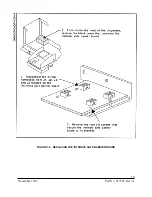
Intrinsic Safe Barrier PCB Replacement (see Figure 7-2)
The Intrinsic Safe Barrier PCB is mounted to the bottom of the electronics
enclosure under a black metal cover.
1. Remove the bezel opposite the junction box side.
2. Remove black metal protective shroud.
3. Remove connectors
4. Remove mounting screws from PCB assembly.
5. Replace with new board using the reverse procedure.
7.1.4.
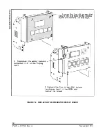
Display Board Replacement (see Figure 7-3)
1. Remove the bezel from the dispenser.
2. Remove the dial face from the display by loosening the four screws in the
corners of the dial face and then slipping it up and off of the display.
3. Disconnect the data cable(s) from the sale display.
4. Remove the screws securing the display assembly. Remove the sale display.
5. Install the new display and secure it with hardware removed in Step 4.
6. Reconnect the data cable(s) from the sale display.
7. Reinstall the dial face and bezel.
Summary of Contents for Vista Series
Page 1: ...SERVICE Vista Blending and Non blending Suction Pumps and Remote Dispensers...
Page 4: ...Part No 917543 Rev A November 1992...
Page 12: ...x Part No 917543 Rev A November 1992...
Page 34: ...22 Part No 917543 Rev A November 1992 FIGURE 4 1 NOZZLE BOOT ASSEMBLY WITH MICRO SWITCH...
Page 35: ...23 November 1992 Part No 917543 Rev A FIGURE 4 2 NOZZLE BOOT ASSEMBLY WITH TILT SWITCH...
Page 36: ...24 Part No 917543 Rev A November 1992...
Page 53: ...41 November 1992 Part No 917543 Rev A FIGURE 5 7 METER CUTAWAY...
Page 54: ...42 Part No 917543 Rev A November 1992 FIGURE 5 8 METER ADJUSTMENT...
Page 58: ...46 Part No 917543 Rev A November 1992...
Page 69: ...57 November 1992 Part No 917543 Rev A FIGURE 7 1 REPLACING THE DUPLEX II COMPUTER...
Page 71: ...59 November 1992 Part No 917543 Rev A FIGURE 7 2 REPLACING THE INTRINSIC SAFE BARRIER BOARD...
Page 72: ...60 Part No 917543 Rev A November 1992 FIGURE 7 3 REPLACING THE INTEGRATED DISPLAY BOARD...
Page 75: ...63 November 1992 Part No 917543 Rev A FIGURE 7 5 REPLACING THE SOLENOID DRIVE BOARD...
Page 82: ...70 Part No 917543 Rev A November 1992...
Page 84: ...72 Part No 917543 Rev A November 1992...
Page 106: ...94 Part No 917543 Rev A November 1992...
Page 110: ...98 Part No 917543 Rev A November 1992 FIGURE B 4 THE DEM IN THE SERVICE POSITION...
Page 112: ...100 Part No 917543 Rev A November 1992 FIGURE B 6 DUPLEX II COMPUTERS J3 CONNECTOR PINOUT...
Page 114: ...102 Part No 917543 Rev A November 1992 FIGURE B 8 DUPLEX II COMPUTERS J11 CONNECTOR PINOUT...
Page 115: ...103 November 1992 Part No 917543 Rev A FIGURE B 9 DUPLEX II COMPUTERS J6 CONNECTOR PINOUT...
Page 116: ...104 Part No 917543 Rev A November 1992 FIGURE B 10 DUPLEX II COMUTERS J1 CONNECTOR PINOUT...
Page 125: ...113 November 1992 Part No 917543 Rev A FIGURE B 18B 4 PRODUCT SOLENOID DRIVE BOARD...
Page 126: ...114 Part No 917543 Rev A November 1992 FIGURE B 18C BLENDER SOLENOID DRIVE BOARD...
Page 133: ...121 November 1992 Part No 917543 Rev A FIGURE B 24 MANUALLY TURNING THE PHOTOCOUPLER...
Page 139: ...127 November 1992 Part No 917543 Rev A FIGURE B 29 LIGHTED CASH CREDIT INTERFACE BOARD...
Page 144: ...132 Part No 917543 Rev A November 1992...
Page 145: ...133 November 1992 Part No 917543 Rev A APPENDIX C DISPENSER INTERNAL WIRING DIAGRAMS...
Page 146: ...134 Part No 917543 Rev A November 1992...
Page 150: ...138 Part No 917543 Rev A November 1992 1 6560 D INTERNAL WIRING DIAGRAM V390D...
Page 151: ...139 November 1992 Part No 917543 Rev A 3 6560 D INTERNAL WIRING DIAGRAM V399D...
Page 152: ...140 Part No 917543 Rev A November 1992 5 6560 D INTERNAL WIRING DIAGRAM V490D...
Page 153: ...141 November 1992 Part No 917543 Rev A 7 6560 D INTERNAL WIRING DIAGRAM V590D...
Page 154: ...142 Part No 917543 Rev A November 1992 9 6560 D INTERNAL WIRING DIAGRAM V387D...
Page 155: ...143 November 1992 Part No 917543 Rev A 11 6560 D INTERNAL WIRING DIAGRAM V390P...
Page 156: ...144 Part No 917543 Rev A November 1992 12 6560 D INTERNAL WIRING DIAGRAM V585D...
Page 157: ...145 November 1992 Part No 917543 Rev A 13 6560 D INTERNAL WIRING DIAGRAM V395D...
Page 160: ...148 Part No 917543 Rev A November 1992...
Page 162: ...150 Part No 917543 Rev A November 1992 FLOWCHART D1 PULSER FAILURE ERROR CODE XX 05 2...


