background image

4

INSTALLATION (ELECTRICAL)

Operating Instructions and Parts Manual

www.waynepumps.com

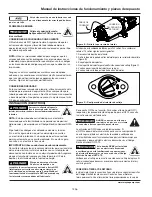
Figure B - Remove back motor cover

This pump is factory wired for 230 volts. To change the voltage to 115 volts 
follow the steps below:
1.  Disconnect the pump from power.
2.  Remove cover from back of motor to find voltage selector (Figure B).
3.  Pull selector knob out.
4.  Rotate selector knob to correct voltage setting (Figure C).
5.  Push selector knob back in place.
6.  Reinstall cover to back of motor.

Figure C - Voltage selector setting

Verify supply voltage matches the nameplate voltage. Incorrect voltage 
can cause fire or seriously damage motor and voids warranty.

GROUNDING/BONDING
Install, ground, bond and wire motor according to local or National 
Electrical Code requirements. Permanently ground the motor. Use ground 
terminal provided in the terminal box on the back of the motor. Use size 
and type wire required by local codes.  Connect motor ground terminal to 
electrical service ground.

Bond motor to swimming pool structure. Bonding connects all metal parts 
within and around the swimming pool with a continuous wire. Bonding 
reduces the risk of current passing between metal objects which could 
cause electrical shock. Reference NEC local codes for all wiring standards. 
Use a solid copper conductor, size No. 8 AWG or larger. Run wire from 
external bonding lug located on top of motor (Figure B) to reinforced rod 
or mesh.

BONDING LUG 

CONNECTION

BONDING WIRE

OPERATION

Prime pump before attempting to operate. To prime pumps located 
above water level, remove strainer cover, fill strainer body with water, then 
replace cover. If pump and all piping are located below water level, the 
pump will self prime. After pump has been primed, energize motor and 
open all suction and discharge line valves. If no flow is observed in five 
minutes, stop the motor and re-prime. If the pump fails to operate, check 
for air leaks. Refer to troubleshooting section. After about 10 minutes 
of operation, check the return fittings for air bubbles. A continuous flow 
of air indicates leaks in the suction line. Locate and correct any leaks 
immediately.


Disconnect, tag, and lock out 


     power source before 

attempting to install, service, relocate or perform any 

maintenance.

NOTE: This pump must be installed by a licensed electrician that 
is familiar with swimming pool/spa operations and in accordance 
with the NFPA 70 – National Electric Code.
Follow all national and local wiring codes. If unsure of code 
requirements consult a professional electrician. Pump must be 
permanently connected to a dedicated circuit. If unsure consult 
a licensed electrician.

IMPORTANT: Use copper conductors only.
Refer to information on motor nameplates for electrical service 
data. Install motors with a fused disconnect switch or a dedicated 
circuit breaker. Be sure wire size is sufficient for pump HP and 
distance from power source.


Electric shock hazard. Connect 


this pump to a properly 

grounded GFCI (Ground Fault Circuit Interrupter) 

receptacle that is rated for at least 15 amps. Test the 

operation of the GFCI receptacle according to the 

manufacturer’s recommended intervals.

GFCI is required in the circuit. For size of GFCI required and test 
procedures for GFCI, see manufacturer’s instructions. 


GFCI tripping indicates an electrical problem. If GFCI trips, determine 
the reason for tripping. If you are uncertain, have a licensed or certified 
electrician that is familiar with swimming pool/spa operations and 
in accordance with the NFPA 70 – National Electric Code inspect 
and repair the electrical system. 


This pump MUST be installed by 


a licensed or certified electrician 

that is familiar with swimming pool/spa operations 

and in accordance with the NFPA 70 - National Electric 

Code.


Suction hazard. Do NOT block 


the pump suction with your 

body. Failure to do so WILL result in death or serious 

bodily injury.

NOTE: Small children using pool must ALWAYS have close adult supervision.


Fire and burn hazard. Motor runs at high 


temperatures, to reduce the risk of fire, do 

NOT allow debris or foreign matter to collect around the pump motor. 

Allow motor to cool prior to handling or performing maintenance.


Do NOT operate pump without strainer. 


     Foreign material may interfere with 

impeller causing pump to stop.


NEVER ground to a gas supply  


      line, use dedicated grounding 


      system

.

Summary of Contents for WIP150

Page 1: ...imming pool pump read and understand ALL guidelines ANSI APSP ICC 15 2011 regarding suction and installation Suction pipe should be as large or larger than discharge pipe Avoid using a suction pipe sm...

Page 2: ...that requires special attention GENERAL SAFETY INFORMATION GENERAL SAFETY 1 Read the manual s included with this product carefully Be thoroughly familiar with the controls and the proper use of the eq...

Page 3: ...imming pool if the drain cover is broken or missing CLOSE the swimming pool or spa Immediately call your swimming pool professional to make repairs Figure A Outlet Cover Certification ENTRAPMENT PROTE...

Page 4: ...e suction line Locate and correct any leaks immediately Disconnect tag and lock out power source before attempting to install service relocate or perform any maintenance NOTE This pump must be install...

Page 5: ...hermal protection circuit to guard against overheating The maximum ambient temperature for motor operation must not exceed rating on motor model plate If the thermal overload protection in the motor t...

Page 6: ...in the Operation section 2 Open the valve 3 Eliminate leaks in suction line 4 Clean strainer see maintenance section 5 Fill swimming pool to proper level Noisy pump and motor 1 Plugged basket in skimm...

Page 7: ...states do not allow limitations on how long an implied warranty lasts or do not allow the exclusions or limitations of incidental or consequential damages so the above lim i ta tions might not apply...

Page 8: ...TES les directives ANSI APSP ICC 15 2011 concernant l aspiration et l installation Le tuyau d aspiration doit tre aussi large ou plus large que le tuyau d vacuation viter d utiliser un tuyau d aspirat...

Page 9: ...un lectricien qualifi pour une installation en bonne et due forme d un circuit avec disjoncteur de fuite de terre Ne PAS laisser les enfants utiliser cette pompe Cette pompe est con ue pour les pisci...

Page 10: ...de chaque raccord d aspiration principal doivent tre s par s d au moins 0 9 m 3 pi l un de l autre Figure A Le syst me doit tre b ti de mani re ce qu il ne puisse pas fonctionner si la pompe aspire de...

Page 11: ...oncteur de fuite de terre indique l existence d un probl me lectrique Si le disjoncteur de fuite de terre se d clenche en d terminer la raison Si vous n tes pas certain de la cause demandez un lectric...

Page 12: ...ont basiques Un pH de 7 0 est neutre Les valeurs de pH inf rieures 7 0 sont acides La fourchette souhaitable est de 7 2 7 4 D brancher tiqueter et verrouiller la source d alimentation avant d installe...

Page 13: ...ite Ne pas utiliser une pression de test de fuite sup rieure 172 kPa 25 PSI une pression sup rieure endommagerait d finitivement la pompe N utiliser que des tuyaux et raccords con us pour les piscines...

Page 14: ...dans la piscine 1 Supprimer les fuites sur la conduite d aspiration 2 Retirer et nettoyer les joints toriques 3 Augmenter la taille de la conduite d aspiration 4 Remplir la piscine un niveau ad quat...

Page 15: ...sent pas de limitations de dur e concernant les garanties tacites ni l exclusion ou la limitation des dommages fortuits ou immat riels Les limitations pr c dentes ne s appliquent donc pas forc ment to...

Page 16: ...DAS las pautas ANSI APSP ICC 15 2011 relacionadas con la succi n e instalaci n La tuber a de succi n debe ser tan grande como la tuber a de descarga o m s grande Evite utilizar una tuber a de succi n...

Page 17: ...on bombas 4 La unidad DEBE estar enchufada a un circuito GFCI correctamente conectado a tierra Consulte con un electricista calificado para obtener informaci n sobre la instalaci n adecuada de un circ...

Page 18: ...ulicamente balanceados con tapas por cada l nea de succi n de bomba de piscina Los centros de los empalmes de succi n de los drenajes principales deben tener al menos 1 m 3 pies de separaci n Figura A...

Page 19: ...fabricante La activaci n del GFCI indica un problema el ctrico Si el GFCI se dispara determine la raz n por la cual se ha disparado Si no est seguro p dale a un electricista licenciado o certificado q...

Page 20: ...cturas del pH por encima de 7 0 son alcalinas Un pH de 7 0 es neutral Las lecturas del pH por debajo de 7 0 son cidas Un rango deseable es de 7 2 a 7 4 Desconecte etiquete y bloquee la fuente de energ...

Page 21: ...I una presi n m s alta da ar la bomba de forma permanente Use nicamente tuber as y conexiones que est n dise adas para piscinas Nunca deje agua en la bomba o el filtro durante condiciones clim ticas d...

Page 22: ...s o en el v stago de la v lvula 2 La tapa del filtro est goteando 3 Hay una restricci n en la l nea de succi n 4 El nivel de agua en la piscina es bajo 1 Elimine las fugas de la l nea de succi n 2 Qui...

Page 23: ...Algunos estados no permiten limitaciones en cuanto a la duraci n de las garant as impl citas o no permiten las exclusiones o limitaciones de da os incidentales o consecuentes de manera que las limita...

Page 24: ...Notes Remarques Notas 24 www waynepumps com...

Reviews: