background image

INSTALLATION

  INSTALLATION OF THIS UNIT MAY TAKE 

SEVERAL HOURS. BEFORE DISABLING YOUR MAIN PUMP, HAVE READY AN 

APPROPRIATE MEANS OF EVACUATING THE SUMP.

1.  Turn power to main pump off.

2.  Pump must be installed using 1-1/4 in. or 1-1/2 in. rigid  
     PVC piping. Do not use flexible hose.

  THIS INSTALLATION MUST BE IN ACCORDANCE WITH 

THE NATIONAL ELECTRIC CODE AND ALL APPLICABLE LOCAL CODES AND 

ORDINANCES.

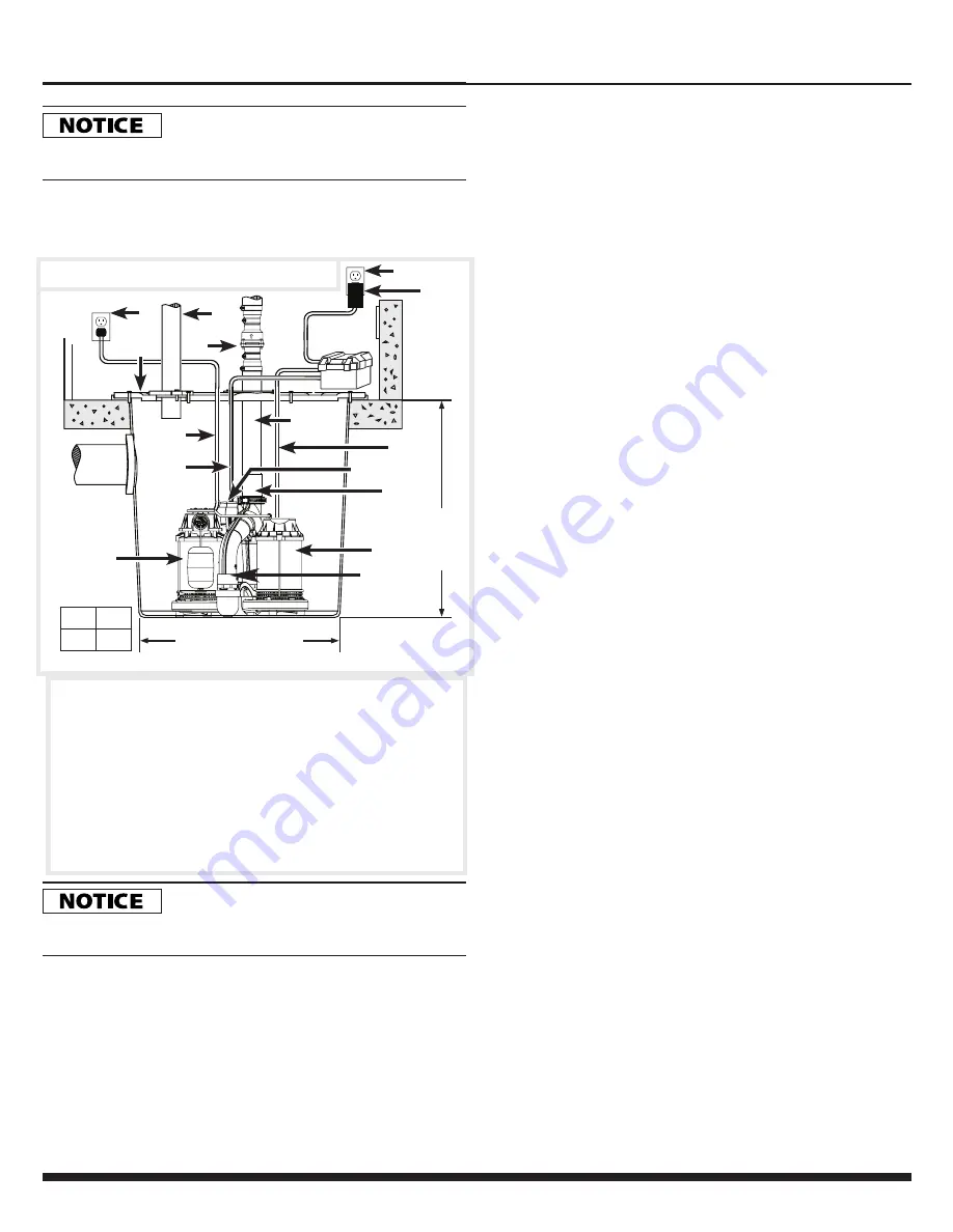
3.  Use a basin (purchased seperately)  or pit that is large enough 

to accommodate the system. The minimum requirements for 
the sump system are shown in Figure 1.

4.  Clean the basin/pit of all debris.
5.  If using a basin, place the system directly on the bottom of 

the basin.To prevent damage set the system on a solid, level 
surface.  Do not place units directly on clay, earth, gravel or 
sand.  A brick or blocks can be installed under the pumps to 
provide a solid base.

6.  Position system so the float switch is away from the inlet 

so float switch is clear from incoming water. Verify the float 
has at least 1 in. clearance to the side wall of the basin and 
is free to move throughout its travel. 

7.  Install discharge plumbing according to local, regional 

and state codes.  Rigid PVC pipe is required. Do not 
use flexible hose in a permanent application. A 1-1/2 
PVC schedule 40 coupling is required on diverter valve 
discharge. Do not use schedule 20 couplings or drainage 
fittings.

8.  Install removable check valve (8) (Wayne Part Number: 

57028-001) positioned just above the basin to allow easy 
removal of the system for cleaning  
and service. Note: A check valve is required to prevent 
back-flow.

9.   Install a gate valve or ball valve if required by local, regional 

or state code.

10.  Connect pump power supply cord to a ground fault circuit 

interrupter (GFCI) outlet (1).

1. GFCI GROUNDED OUTLETS
2. AC PUMP POWER CORD
3. DC PUMP POWER CORD
4. DISCHARGE PIPE
5. AC PUMP (Primary)
6. DC PUMP (Secondary)
7. VENT PIPE
8. REMOVABLE CHECK VALVE

9. GASKET/BASIN LID
10. BATTERY BOX CONTROLLER 
11. DC FLOAT SWITCH
12. DC FLOAT SWITCH CORD
13. TRANSFORMER
14. 11/2” PVC SCHEDULE 40 

COUPLING

15. DIVERTER VALVE

Figure 1: Submersible Sump System

1

15

3

5

8

9

6

15 IN. DIAMETER MIN.

14

4


10

12

13

11

MINIMUM 

BASIN

DEPTH

(22 IN.)

ON 

LEVEL

AC

9"

10"

NA

4"

DC

OFF 

LEVEL 

2

7

1

Operating Instructions and Parts Manual

5

www.waynepumps.com

WSS30Vn

Summary of Contents for WSS30Vn

Page 1: ...c SHAFT Steel Stainless Steel DISCHARGE 1 1 2 in NPT Submersible Sump Pump System www waynepumps com Intended for Indoor Use Only Please read and save these instructions Read carefully before attempti...

Page 2: ...cause damage to equipment IMPORTANT SAFETY INFORMATION RISK OF ELECTRIC SHOCK TO REDUCE THIS RISK OBSERVE THE FOLLOWING WARNINGS RISQUE DE CHOC LECTRIQUE POUR R DUIRE CE RISQUE TENIR COMPTE DES AVERT...

Page 3: ...CORD OR SURGE PROTECTOR Extension cords and or surge protectors could present a safety hazard if not sized properly become damaged or the connection falls into the sump If receptacle is not within rea...

Page 4: ...and water Si de l acide de batterie entre en contact avec les yeux les rincer avec de l eau courante froide pendant 10 minutes et consulter imm diatement un m decin Si l acide entre en contact avec l...

Page 5: ...and is free to move throughout its travel 7 Install discharge plumbing according to local regional and state codes Rigid PVC pipe is required Do not use flexible hose in a permanent application A 1 1...

Page 6: ...onnectors The connections are all unique and cannot be interchanged FLOOR JOIST RIGID PVC PIPE TRANSFORMER REQUIRED CHECK VALVE SEE STEP 3 7 BATTERY BOX PRIMARY AC PUMP BACKUP DC PUMP SLOPE PIPE DOWN...

Page 7: ...tery voltage particularly with a defective battery In order for the indicator light to provide an accurate reading steps a through d must be followed Risk of electrical shock Unplug main ac pump and t...

Page 8: ...incorrect motor conditions or at the end of its life AC ROUTINE SUMP MAINTENANCE The pump system should be inspected 3 4 times per year for movement or buildup of debris on the switch or float Reposi...

Page 9: ...ion to ensure free motion of switch 4 Remove obstruction in discharge piping 5 Contact an electrician Pump operates noisily or vibrates excessively 1 Worn bearings 2 Impeller broken 3 Piping attachmen...

Page 10: ...e as needed 3 Make sure nothing is interfering with operation of switch 4 Pull the transformer from the wall outlet and remove Check the 20 Amp Automotive Sytle fuse located under the battery box lid...

Page 11: ...e Harrison OH 45030 U S A REPAIR KITS MODEL ALL MODELS REF NO DESCRIPTION PART NUMBER 1 FLOAT KIT 60038 WYN1 2 TRANSFORMER 60194 WYN1 3 BACK UP SWITCH Call for part 4 LID ASSEMBLY 60184 WYN1 4 2 1 3 1...

Page 12: ...SALE OF THE PRODUCT THE REMEDIES AND OBLIGATIONS STATED IN THIS WARRANTY ARE THE SOLE AND EXCLUSIVE REMEDIES OF AND OBLIGATIONS TO THE OWNER FOR ANY AND ALL MATTERS ARISING WITH RESPECT TO OR IN ANY...

Reviews: