background image

Web Operation   

High-Resolution IR Camera 

User Manual 


32 


Issue  V1.0  (2018-05-11) 


Parameter 

Description 

Setting 

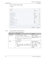
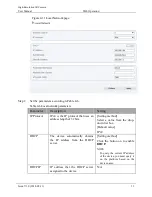
IP Address 

Device IP address that can be set as 
required. 

[Setting method] 

Enter a value manually.   

[Default value] 

192.168.1.64 

Subnet Mask 

Subnet  mask  of  the  network 
adapter. 

[Setting method] 

Enter a value manually. 

[Default value] 

255.255.255.0 

Default 
Gateway 

This  parameter  must  be  set  if  the 
client accesses the device through a 
gateway. 

[Setting method] 

Enter a value manually. 

[Default value] 

192.168.1.1 

Preferred 
DNS Server 

IP address of a DNS server. 

[Setting method] 

Enter a value manually. 

[Default value] 

8.8.8.8 

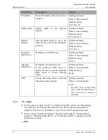
Alternate 
DNS Server 

IP address of a domain server. 

If  the  preferred  DNS  server  is 
faulty,  the  device  uses  the  alternate 
DNS  server  to  resolve  domain 
names. 

[Setting method] 

Enter a value manually. 

[Default value] 

blank 

MTU 

Set  the  maximum  value  of  network 
transmission data packets. 

[Setting method] 

Enter a value manually.   

NOTE 

The  MTU  value  is  range  from 
800 to 1500, the default value is 
1500,  Please  do  not  change  it 
arbitrarily. 


Step 3


Click 

Apply


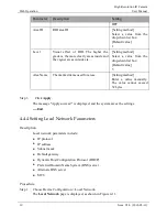
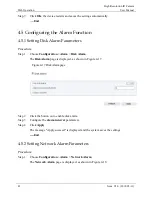
If the message "Apply success!" is displayed, and the system saves the settings. 
The message "Set network parameter success, Please login system again" is 
displayed. Use the new IP address to log in to the web management system. 


If the message "Invalid IP Address", "Invalid Subnet Mask", "Invalid default 
gateway", "Invalid primary DNS", or "Invalid space DNS" is displayed, set the 
parameters correctly. 

----End 

Summary of Contents for 0E-13BF36

Page 1: ...ution IR Camera User Manual If you have any questions please call W Box Tech Support 1 833 574 9124 for assistance E mail tech wboxsupport com 0E 13D28 0E 13BF36 0E 21D28WDR 0E 21BF36WDR 0E 40D28WDR 0E 40BF36WDR ...

Page 2: ......
Page 3: ...g symbols whose meanings are described accordingly Symbol Description It alerts you to fatal dangers which if not avoided may cause deaths or severe injuries It alerts you to moderate dangers which if not avoided may cause minor or moderate injuries It alerts you to risks Neglect of these risks may cause device damage data loss device performance deterioration or unpredictable results It provides ...

Page 4: ...heavy loads intensive shakes and soaking to prevent damages during transportation and storage The warranty does not cover any device damage that is caused during secondary packaging and transportation after the original packaging is taken apart Protect this device from fall down and intensive strikes keep the device away from magnetic field interference and do not install the device in places with...

Page 5: ...echnology information that is not accurate enough or product function and operation description that is slightly inconsistent with the actual product The manufacturer will update this manual according to product function enhancement or changes and regularly update the software and hardware described in this manual Update information will be added to new versions of this manual without prior notice...

Page 6: ...e Information 21 4 4 Setting Video and Audio Stream Parameters 23 4 4 2 Setting SVC Stream Parameters 27 4 4 3 Region of Interest 28 4 4 4 Setting Local Network Parameters 30 4 4 5 Configuring Device Ports 33 4 4 6 Configuring the Date and Time 34 4 4 7 Setting the Channel Name Video System and Source Resolution 37 4 4 8 Setting OSD Parameters 38 4 4 9 System Service 41 4 5 Configuring the Alarm F...

Page 7: ... Parameters 60 4 8 7 Setting IP Filter Parameters 62 4 8 8 Setting CGI Alarm Service Center Parameters 65 4 8 9 Setting SNMP Parameters 68 4 9 Privilege Manager 71 4 10 Configuring Protocol Parameters 75 4 10 1 Checking Protocol Information 75 4 10 2 Setting Security Authentication 75 4 10 3 Setting Multicast Parameters 76 4 11 Querying Operation Logs 78 4 11 2 Querying Operation Logs 78 4 11 3 Qu...

Page 8: ... 1 1 shows the power and network cables Figure 1 1 Power and network cables Table 1 1 shows the description of the cable Table 1 1 description of the cable ID Core Description 1 Network access port Connects to a standard Ethernet cable 2 Power supply DC 12V Connects to a 12V 15 10 direct current DC power supply ...

Page 9: ...E 13D28 and 0E 21D28WDR Figure 2 1 Dimensions of 0E 13D28 and 0E 21D28WDR unit mm Figure 2 2 shows the camera dimensions of 0E 40D28WDR Figure 2 2 Dimensions of 0E 40D28WDR unit mm 2 2 Device Installation Step 1 Open a package take out the camera unscrew the camera compression ring and disassemble the camera the camera components is shown in Figure 2 3 ...

Page 10: ...amera components Step 2 Use the base as drill template drill holes on the ceiling or wall and reserve the cable entries of the video power cables Figure 2 4 and Figure 2 5 shows the dimensions of the camera mounting base Figure 2 4 Dimensions of the 0E HDD1MP28 and 0E HDD2MP28 mounting base ...

Page 11: ...drilled holes and fix the camera mounting base to the ceiling or wall by use of self tapping screws Step 4 Install the compression ring the dome shell and the dome shell fixed base on the camera mounting base Figure 2 6 shows camera installation Figure 2 6 Camera installation Step 5 Turn the main body adjust the lens direction and note the position of the dome cover window ...

Page 12: ...le and power cable Adjust the position of the camera by triaxial rotation rotating horizontally rotating up and down and performing lens axial rotation and adjust the camera direction and lens alignment target Figure 2 7 shows monitoring direction adjustment Figure 2 7 Monitoring direction adjustment Step 6 Use soft cloth to wipe the lens front glass which is likely to be soiled due to installatio...

Page 13: ...ser Manual Bullet camera Issue V1 0 2018 05 11 11 3 Bullet camera 3 1 Dimensions Figure 3 1 shows the dimensions of 0E 40BF36WDR Figure 3 1 dimensions of 0E 40BF36WDR Figure 3 2 shows the dimensions of 0E 13BF36 and 0E 21BF36WDR ...

Page 14: ...n Step 1 Stick the Installation location sticker on the ceiling or wall Drill three holes based on the marks on the sticker Drive the swell plastic buttons into the holes as shown in Figure 3 3 Figure 3 3 Drilling holes Step 2 Loosen the locking screw with L Hex Wrench and rotate the camera then attach the camera to the surface as shown in Figure 3 4 ...

Page 15: ...ting cable Step 4 Loosen the locking screw with L Hex Wrench rotate the camera to adjust the position and image so that the camera faces the monitored area then tighten the locking screw as shown in Figure 3 6 To rotate the part 1 of the camera for 360 loosen rotation lock To rotate the part 2 of the camera for180 loosen screw 1 To rotate the part 3 of the camera for 360 loosen screw 2 ...

Page 16: ...Bullet camera High Resolution IR Camera User Manual 14 Issue V1 0 2018 05 11 Figure 3 6 Adjusting monitored area End ...

Page 17: ...net Explorer 7 and more to access the web management system otherwise some functions may be unavailable Login Step 1 Open Internet Explorer enter the IP address of the IP camera default value 192 168 1 64 in the address box and press Enter The login page is displayed as shown in Figure 4 1 Figure 4 1 Login page Step 2 Enter the user name and password ...

Page 18: ... 3 Click The main page is displayed End Logout To log out of the system click in the upper right corner of the main page The login page is displayed after you log out of the system 4 1 2 Changing the Password Description The change password page will be displayed as shown in Figure 4 2 when you login the system for the first time Figure 4 2 Change the default password page Or click to change the p...

Page 19: ...password is successfully changed If the password fails to be changed the cause is displayed For example the new password length couldn t be less than eight Step 3 Click OK The login page is displayed 4 1 3 Main Page Layout On the main page you can view real time videos receive alarm and fault notifications set parameters change the password and log out of the system Figure 4 4 shows the main page ...

Page 20: ...s in this area NOTE Only when the SD card or NAS have videos that you can query the playback videos 3 Device configuration You can choose a menu to set device parameters including the device information audio and video streams alarm setting and privacy mask function 4 Alarm icon When the device generates an alarm the alarm icon is displayed You can click the icon to view the alarm information NOTE...

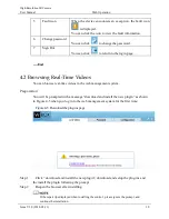
Page 21: ... You can browse real time videos in the web management system Preparation You will be prompted with a message download and install the new plugin as shown in Figure 4 5 when you log in to the web management system for the first time Figure 4 5 Download the plug ins page Step 1 Click download and install the new plugin download and setup the plug ins and the install the plugin following the prompt ...

Page 22: ...gure 4 6 Live Video page On the Live Video page you can perform the following operations Click to stop playing a video Click to play a video Double click in the video area to enter the full screen mode and double click again to exit Switch among preset streams 1 2 and 3 For details about how to configure streams see Setting Video and Audio Stream Parameters Click to snapshot and save the photos ...

Page 23: ...alance focus setting Iris setting white balance and noise filter as prompted 4 3 Configuring the Device 4 3 1 Configuring the Device Information Description The device information includes Device ID name type model and MAC address Hardware and software versions Number of video channels number of alarm input channels number of alarm output channels and number of serial ports You can modify the devi...

Page 24: ...ription Setting Device ID Unique device identifier used by the platform to distinguish the devices Setting method These parameters cannot be modified Device Name Name of the device NOTE The device name cannot exceed 32 bytes or 10 simplified characters otherwise the modification fails Setting method Enter a value manually MAC Address N A Setting method These parameters cannot be modified Camera Ty...

Page 25: ...uantity Network card Quantity Step 3 Click If the message Apply success is displayed click OK The system saves the settings If the message Apply failed is displayed you must apply for the Parameter Configure permission from an administrator For details see 4 10 1 4 4 Setting Video and Audio Stream Parameters Procedure Step 1 Click Configuration Stream Base Stream The Stream Configuration page is d...

Page 26: ...arameter Description Setting Stream ID The device supports 3 streams Streams 1 and 2 use the H 264 codec The maximum resolution can be set for streams 1 Setting method Select a value from the drop down list box Name Stream name NOTE The stream name is combined with Chinese character number character and underline Setting method Enter a value manually The value cannot exceed 32 bytes Default value ...

Page 27: ... profile The performance of H 264 High Profile is higher than that of H 264 Main Profile and the performance of H 264 Main Profile is higher than that of H 264 Base Profile If a hardware decoding device is used select the appropriate codec based on the decoding performance of the device H 264 High Profile has the highest requirements on the hardware performance and H 264 Base Profile has the lowes...

Page 28: ...n 22 5 f s is considered as smooth by human eyes Frame rates for different frequencies are as follows 50 Hz 1 25 f s 60 Hz 1 30 f s NOTE The frequency is set on the Device Configuration Camera page The biggest MJPEG coding format frame rate is 12 frames per second Setting method Select a value from the drop down list box I Frame Interval Unit Fr ame I frames do not require other frames to decode A...

Page 29: ...n list box Step 3 Click Apply If the message Apply success is displayed and the system saves the settings If the message Apply failed is displayed you must apply for the Parameter Configure permission from an administrator For details see4 10 1 4 4 2 Setting SVC Stream Parameters Procedure Step 1 Click Configuration Stream SVC Stream The SVC Stream page is displayed as shown in Figure 4 9 Figure 4...

Page 30: ...he elementary stream Setting method Select a value from the drop down list box P Frame Rate The P frame rate of SVC stream and elementary stream Setting method Select a value from the drop down list box Step 3 Click Apply If the message Apply success is displayed and the system saves the settings If the message Apply failed is displayed you must apply for the Parameter Configure permission from an...

Page 31: ...figuration page Step 2 Set the parameters according to Table 4 5 Table 4 5 ROI configuration parameters Parameter Description Setting Stream Stream ID Setting method Select a value from the drop down list box Default value Stream1 Enable Enable the ROI Setting method Click the button Default value ...

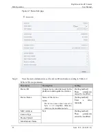
Page 32: ...fault value 5 Area Name The marked name used for areas Setting method Enter a value manually The value cannot exceed 32 bytes Step 3 Click Apply The message Apply success is displayed and the system saves the settings End 4 4 4 Setting Local Network Parameters Description Local network parameters include IP protocol IP address Subnet mask Default gateway Dynamic Host Configuration Protocol DHCP Pr...

Page 33: ...4 is the IP protocol that uses an address length of 32 bits Setting method Select a value from the drop down list box Default value IPv4 DHCP The device automatically obtains the IP address from the DHCP server Setting method Click the button on to enable DHCP NOTE To query the current IP address of the device you must query it on the platform based on the device name DHCP IP IP address that the D...

Page 34: ...ate DNS Server IP address of a domain server If the preferred DNS server is faulty the device uses the alternate DNS server to resolve domain names Setting method Enter a value manually Default value blank MTU Set the maximum value of network transmission data packets Setting method Enter a value manually NOTE The MTU value is range from 800 to 1500 the default value is 1500 Please do not change i...

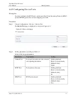
Page 35: ...t The Device Port page is displayed as shown in Figure 4 12 Figure 4 12 Device Port page Step 2 Set the parameters according to Table 4 7 Table 4 7 Device port parameters Parameter Description Setting Control Port Port used for audio and video transfer and signaling interaction Setting method Enter a value manually Default value 30001 HTTP Port Port used in web access Setting method Enter a value ...

Page 36: ...e settings If the message Invalid Control Port Please input an integer between 1025 and 65535 is displayed enter correct port numbers End 4 4 6 Configuring the Date and Time Description On the Date and Time page you can modify the date and time Parameters that can be set include Time zone and daylight saving time DST Date and time Network Time Protocol NTP server Procedure Step 1 Choose Configurat...

Page 37: ...Web Operation Issue V1 0 2018 05 11 35 Figure 4 13 Date and Time page Table 4 8 Date and Time parameters Parameter Description Setting Time Zone N A Setting method Select a value from the drop down list box Default value Greenwich mean time ...

Page 38: ...to enable Daylight Saving Time Device Time Device display time Setting method Synchronize the time from the PC Enter a value manually Current PC Time Time on the current PC N A Set Manually Enables you to manually set the device time Setting method Click Set Manually and set the date and time in the format MM DD YYYY HH MM SS NTP IP address or domain name of the NTP server Setting method Click the...

Page 39: ...ice time Click Set Manually A time setting control is displayed Set the date and time Step 5 Configure the NTP 1 Click the button on to enable NTP 2 Enter the IP address or domain name of the NTP server the port number and the time interval Step 6 Click The message Apply success is displayed and the system saves the settings End 4 4 7 Setting the Channel Name Video System and Source Resolution Pro...

Page 40: ...s follows 50 Hz corresponds to the PAL system 60 Hz corresponds to NTSC system Setting method Corresponds to the video system Step 2 Enter a channel name The channel name must be within the length of 0 to 32 bytes it is combined with digital and character except for some special character Step 3 Click The message Apply success is displayed If the video system is modified the message The device wil...

Page 41: ...ly The OSD support simplified Chinese English digital and some special character only Procedure Step 1 Choose Configuration Device OSD The OSD page is displayed as shown in Figure 4 15 Figure 4 15 OSD page Step 2 Set the parameters according to Table 4 10 The size of characters that can be displayed in a row or column varies according to the resolution When the OSD font is auto ...

Page 42: ...cription Setting Time Indicates whether to display the time Setting method Tick the time Custom OSD Enables you to enter a line of characters Setting method 1 Tick the custom OSD list 2 Enter the characters 3 Click to save the value Time Format Format in which the time is displayed Setting method Select a value from the drop down list box Default value YYYY MM DD hh mm ss ww Font Color Set the fon...

Page 43: ...played And the system saves the settings End 4 4 9 System Service Procedure Step 1 Choose Configuration Device System The System Service page is displayed as shown in Figure 4 16 Figure 4 16 System Service page Step 2 Select a language from the Language drop down list box Step 3 Click the message Apply success is displayed Step 4 Click OK the system saves the settings Step 5 Select a Web Mode from...

Page 44: ...uration Alarm Disk Alarm The Disk Alarm page is displayed as shown in Figure 4 17 Figure 4 17 Disk Alarm page Step 2 Click the button on to enable disk alarm Step 3 Configure the alarm interval parameters Step 4 Click Apply The message Apply succeed is displayed and the system saves the settings End 4 5 2 Setting Network Alarm Parameters Procedure Step 1 Choose Configuration Alarm Network Alarm Th...

Page 45: ...ayed and the system saves the settings End 4 5 3 Setting Motion Alarm Parameters Description On the Motion Alarm page you can perform the following operations Enable the motion alarm function Set the motion alarm interval Set the motion detection area Set motion alarm the sensitivity Configure the motion alarm output channel When the alarm output function is enabled and the camera detects that an ...

Page 46: ...tion Alarm page Step 2 Click the button on to enable motion alarm Step 3 Configure the motion interval Step 4 Configure the sensitivity Step 5 Configure the schedule time setting Method 1 Click left mouse button to select any time point within 0 00 24 00 from Monday to Sunday as shown in Figure 4 19 Method 2 Hold down the left mouse button drag and release mouse to select the schedule within 0 00 ...

Page 47: ...inverse selection to delete the selected schedule Step 6 Configure the detection area Press and hold the left mouse button and drag in the video area to draw a detection area as shown in Figure 4 20 Figure 4 20 Motion Area Setting page Click Clear to delete a detection area Step 7 Click Apply The message Apply succeed is displayed the system saves the settings End 4 5 4 Setting push message Parame...

Page 48: ...utton on to enable push message Step 3 Click Apply The message Apply succeed is displayed and the system saves the settings End 4 6 Configuring the Recording Function 4 6 1 Configuring a Recording Policy You can configure the scheduled recording function alarm recording function recording quality and recording rules Procedure Step 1 Choose Configuration Device Record Record Policy The Record Polic...

Page 49: ... Setting method Click the button on to enable schedule record Default value OFF Post Record Recording duration in seconds after an alarm is generated Setting method Enter a value manually Record Rule Rule for saving recordings The options are as follows Cycle Store Saves recordings in cycles Save Days Duration in days for saving a recording The duration can be a maximum of 99999 days NOTE The valu...

Page 50: ... videos around the clock or in schedule For details about how to set Schedule see 4 5 3 Step 5 Step 4 Click Apply If the message Apply success is displayed the system saves the settings If other information is displayed set the parameters correctly End 4 6 2 Configuring a Recording Directory Description Recordings can be stored in a NAS Procedure Step 1 Choose Configuration Device Record Record Di...

Page 51: ...type which can be a NAS Setting method The parameter cannot be set manually Disk ID Indicates the Disk ID Group ID Indicates the group HID Enable Indicates whether to enable the recording directory Total Space Total disk space Usable Space Maximum disk space read automatically Alarm Threshold The camera will alarm when used Space achieves the alarm threshold State Status of the connection between ...

Page 52: ...ayed as shown in Figure 4 24 Figure 4 24 SD card Record Path Modify page Step 3 Set the parameters according to Table 4 13 Table 4 13 SD card recording parameters Parameter Description Setting NAS Enable NAS to enable record Setting method Click button to enable NAS IP Address IP address of NAS Setting method Enter a value manually Path Path of NAS User Name N A Password Confirm File System Settin...

Page 53: ...d and the system saves the settings End 4 7 Configuring the Privacy Mask Function Procedure Step 1 Choose Configuration Privacy Masking The Privacy Masking page is displayed as shown in Figure 4 25 Figure 4 25 Privacy Masking page Step 2 Press and hold the left mouse button and drag on the preview image to cover the part to be masked ...

Page 54: ...g N A Name Name of privacy Masking Setting method Click the name and enter a value manually Default value Blank Type Type of privacy masking Setting method Select a value from the drop down list box Default value Color Block Color Color of privacy masking Setting method Select a value from the drop down list box Default value Black Enable Indicates whether to enable the privacy masking Setting met...

Page 55: ...s modified successfully Step 4 Click Apply The message Apply success is displayed and the system saves the settings End 4 8 Configuring the Network Service 4 8 1 Setting 802 1x Parameters Preparation 802 1x authentication must be configured on the access port which controls to access network resources for the connected user devices on the port Procedure Step 1 Choose Configuration Network Service ...

Page 56: ...n Connect the specified camera to the Internet and obtain the user name and password for logging into the Dynamic Domain Name System DDNS server Procedure Step 1 Choose Configuration Network Service DDNS The DDNS page is displayed as shown in Figure 4 27 Figure 4 27 DDNS page Step 2 Click the button on to enable DDNS Step 3 Set the parameters according to Table 4 15 Table 4 15 DDNS parameters Para...

Page 57: ... Click Test if the device connects to DDNS successfully the message Test CGI alarm success is displayed Step 4 Click Apply If the message Apply success is displayed and the system saves the settings If other information is displayed set the parameters correctly End 4 8 3 Setting PPPoE Parameters Preparation Obtain the PPPoE user name and password from the network carrier Description If a PPPoE con...

Page 58: ...er name of PPPoE provided by the network carrier Setting method Enter a value manually Password Password of PPPoE provided by the network carrier Setting method Enter a value manually Step 4 Click Apply If the message Apply success is displayed and the system saves the settings If other information is displayed set the parameters correctly End 4 8 4 Setting Port Mapping Parameters Description With...

Page 59: ...utton on to enable Port Mapping Step 3 Set the parameters according to Table 4 17 Table 4 17 Port mapping parameters Parameter Description Setting Port Mapping Indicates whether to enable the Port Mapping service Setting method Click the button on Default value OFF Map Mode Mode of port mapping includes auto and manual Setting method Select a value from the drop down list box Default value Auto Po...

Page 60: ...message Apply success is displayed and the system saves the settings If other information is displayed set the parameters correctly End 4 8 5 Setting SMTP Parameters Description If the Simple Mail Transfer Protocol SMTP function is enabled the device automatically sends JPG images and alarm information to specified email addresses when an alarm is generated Procedure Step 1 Choose Configuration Ne...

Page 61: ...eters Parameter Description Setting SMTP Server Address IP address of the SMTP server Setting method Enter a value manually SMTP Server Port Port number of the SMTP server Setting method Enter a value manually Default value 25 User Name User name of the mailbox for sending emails Setting method Enter a value manually Password Password of the mailbox for sending emails Setting method Enter a value ...

Page 62: ...ess of recipient 5 Attachment Image Quality A higher quality image means more storage space Set this parameter based on the site requirement N A Transport Mode Email encryption mode Set this parameter based on the encryption modes supported by the SMTP server Setting method Select a value from the drop down list box Default value No Encrypted Step 3 Click Apply If the message Apply success is disp...

Page 63: ...Description Setting FTP Upload Indicates whether to enable the FTP service Setting method Click the button on Default value OFF FTP Address IP address of FTP server Setting method Enter a value manually FTP Port Port of FTP server Setting method N A Default value 21 Account FTP server account Setting method Enter a value manually Password FTP server Password Setting method Enter a value manually F...

Page 64: ... the drop down list box Default value Mid Step 4 Click Apply If the message Apply success is displayed and the system saves the settings If other information is displayed set the parameters correctly End 4 8 7 Setting IP Filter Parameters Description Set the IP address in specified network segment to allow access or prohibit access Procedure Step 1 Choose Configuration Network Service IP Filter Th...

Page 65: ...p 3 Set the parameters according to Table 4 20 Table 4 20 IP Filter parameters Parameter Description Setting IP Filter Indicates whether to enable the IP Filter Setting method Click the button on Default value OFF Rule Type IP filter type includes black list and white list Setting method Select a value from the drop down list box Default value Black List ...

Page 66: ...white list page as shown in Figure 4 33 2 Enter Begin IP Address 3 Enter End IP Address 4 Enter Description 5 Click OK the black list added successfully White List Specified network segment to prohibit access Setting method 1 Click to enter the add black white list page as shown in Figure 4 33 2 Enter Begin IP Address 3 Enter End IP Address 4 Enter Description 5 Click OK the white list added succe...

Page 67: ...ll push the alarm message by CGI with Start URL and End URL and send to data to CGI Server by HTTP protocol CGI alarm message is the head of User Agent of HTTP Use HTTP protocol get and send to CGI Server When need to integrate the CGI alarm message need to resolve the HTTP Head User Agent to get the data of CGI alarm message Procedure Step 1 Choose Configuration Network Service CGI Alarm Service ...

Page 68: ...he parameters according to Table 4 21 Table 4 21 CGI Alarm Service Center parameters Parameter Description Setting CGI Alarm Indicates whether to enable the CGI Alarm Setting method Click the button on Default value OFF Name Name of CGI Alarm Setting method Enter a value manually Type Type of CGI Alarm Setting method Select a value from the drop down list box Default value HTTP ...

Page 69: ...lly Password Password of device Setting method Enter a value manually Proxy Setting Indicates whether to enable the Proxy Forwarder server of CGI alarm to forward the CGI alarm Setting method Click the button on Default value OFF Address IP address of Forwarder server Setting method Enter a value manually Port Port of Forwarder server Setting method Enter a value manually platform User Name User n...

Page 70: ...iption Simple Network Management Protocol SNMP is an Internet Standard protocol supports SNMP v1 SNMPv2c and SNMPv3 network protocol Choose the proper SNMP protocol version and set the SNMP protocol parameter to collect and organize information about managed devices on IP networks Procedure Step 1 Choose Configuration Network Service SNMP The SNMP page is displayed as shown in Figure 4 35 ...

Page 71: ...solution IR Camera User Manual Web Operation Issue V1 0 2018 05 11 69 Figure 4 35 SNMP page Step 2 Click the button on to enable SNMPv1 SNMPv2C and SNMPv3 Table 4 22 Set the parameters according to Table 4 23 ...

Page 72: ...p Trap Community community string of trap The trap community string allows the manager to receive asynchronous information from the agent SNMPv3 Version of SNMP SNMPv3 uses community strings but allows for secure authentication and communication between SNMP manager and agent Setting method Click the button on Default value OFF Read Security Name Name of read security Setting method Enter a value ...

Page 73: ...t value Blank Encry Password Encryption password Setting method Enter a value manually SNMP Port Port of SNMP Setting method Enter a value manually Default value 161 Step 3 Click Apply The message Apply success is displayed and the system saves the settings End 4 9 Privilege Manager Description You can add modify and delete a user in privilege manager page Procedure Step 1 Choose Configuration Pri...

Page 74: ...elongs The default permission groups are Super Admin Administrators Operator and Media user Their permissions are described as follows Super Admin Includes all privileges Administrators Live Video Video Control PTZ control Audio Playback Backup Record Policy Disk Configure Privilege Manage Parameter Configure System Maintenance and Log Operator System Maintenance Parameter Configure playback Live ...

Page 75: ...he operations Table 4 25 Operation description Function Procedure Description Add 1 Click Add The Add User page is displayed as shown in Figure 4 37 2 Enter a user name password confirm password 3 Select a group from the drop down list box 4 Enter the notes Optional 5 Check the privilege 6 Click OK The user is added successfully Add an administrator or a common user as shown in Figure 4 37 Modify ...

Page 76: ... Manual 74 Issue V1 0 2018 05 11 Function Procedure Description Delete Select the user from the User list Click the message Confirm to delete is displayed click OK then the group is deleted successfully Delete a user Figure 4 37 Add user page End ...

Page 77: ...eters Figure 4 38 Protocol Info page Table 4 26 Protocol related parameters Parameter Description Protocol Name Type of the access protocol Protocol Version Version number of the access protocol Protocol Software Version Software version number of the access protocol RTSP Rule URL rule of Real Time Streaming Protocol RTSP Example URL example of Real Time Streaming Protocol 4 10 2 Setting Security ...

Page 78: ...ging in to the device web page NOTE The default user name is admin and the default password is admin Setting method Click the button on to enable User Verification Step 2 Click Apply A dialog box is displayed indicating the parameter configuration success To make the configuration take effect click Confirm to restart the device End 4 10 3 Setting Multicast Parameters Description You can set multic...

Page 79: ...alue 1 IP IP address that receive multicast data Setting method Enter a value manually Default value 238 255 255 255 Video Port Port that receive video data Setting method Enter a value manually Default value 25330 Source Port Port that receive source data Setting method Enter a value manually Default value 25530 Step 2 Click Apply The message Apply success effective after restart is displayed whe...

Page 80: ...t system maintenance device configuration recording operation video control and real time video 4 11 2 Querying Operation Logs Procedure Step 1 Choose Configuration Device Log Operation Log The Operation Log page is displayed as shown in Figure 4 41 Figure 4 41 Operation Log page Step 2 Set the search criteria 1 Select the type of operation logs to be queried from the System Log drop down list box...

Page 81: ... Please download log by save as in the right key are displayed 3 Right click the link and save the logs An operation log is named as Operation Log by default and in the following format Operation time user User name Operation information For example 2012 06 20 13 40 39 user StartUpDevice 2012 06 20 13 42 46 user admin ConfigureDeviceName 2012 06 20 13 43 16 user admin ConfigureAlarmIn End 4 11 3 Q...

Page 82: ...to be queried from the Alarm Type drop down list box Step 3 Click Query The alarm logs of the specified type are displayed Step 4 Download the alarm logs 1 Set the start time and end time 2 Select a log type 3 Click Download on the right of the page The log link and the message Please download log by save as in the right key are displayed 4 Right click the link and save the logs An alarm log is na...

Page 83: ...ation logs alarm logs upgrade logs and debugging logs Procedure Step 1 Choose Configuration Device Log Collect all Log The Collect all log page is displayed as shown in Figure 4 43 Figure 4 43 Collect Log page Step 2 Collect logs with one click 1 Click Collect the download page is displayed 2 Select the path to save the logs End 4 12 Maintaining the Device 4 12 1 Restarting a Device Description Yo...

Page 84: ... is restarted successfully five minutes later End 4 12 2 Updating the software package Description You can update the software package from web Procedure Step 1 Choose Configuration Maintenance The Device Maintenance page is displayed Step 2 Click to select the upgrade file Step 3 Click Update If the message Upgrade success The device is rebooting please login late is displayed the grogram update ...

Page 85: ...se whether to reserve the IP address will be restored to the factory settings Use this function carefully Procedure Step 1 Choose Maintenance The Device Maintenance page is displayed Step 2 Click the button to enable Reserve IP setting Reserve IP address of the device Restore to default IP address of the device Step 3 Click The message Are you sure to restore is displayed Step 4 Click OK The devic...

Page 86: ...Local Config page Step 2 Select snapshot picture format from the drop down box Step 3 Set snapshot save path Step 4 Set local record save path Step 5 Set local record file size 8 128M the default value is 64 Step 6 The message Apply success is displayed and the system saves the settings End ...

Page 87: ... IR LED ON Day Night ICR Shutter Speed 1 5 1 20000 Auto Iris Fixed Wide Dynamic Range WDR 120dB Digital Noise Reduction 2D 3D Lens 2 8mm 3 6mm FOV 90 85 IR LED 18pcs IR Range 30m IMAGE Video Compression H 265 H 264 MJPEG Bit Rate CBR VBR Main stream 1080P 500Kbps 12Mbps 720P 200Kbps 8Mbps Sub stream 100kb 6000kb Audio Compression G 711 RAW_PCM Max Resolution 1920 1080 30fps Stream Stream 1 1920 10...

Page 88: ...ideo Standard RFC2326 Support QuickTime VLC Player Security User security authentication Reset Hardware Watch Dog Web Language English Chinese Polish Italian Portuguese Spanish Russian French Czech Hungarian System Compatibility Onvif Interface Ethernet 1 Ethernet 10 100 Base T RJ 45 Connector GENERAL Power Supply DC12V POE Power Consumption 2 5W IR LED OFF 5W IR LED ON Operating Temperature Start...

Page 89: ...o Iris Fixed Wide Dynamic Range dWDR Digital Noise Reduction 2D 3D Lens 2 8mm 3 6mm FOV 90 85 IR LED 18pcs IR Range 30m IMAGE Video Compression H 264High Main Baseline Profile MJPEG Bit Rate CBR VBR Mainstream 500kb 12000kb Sub stream 100kb 6000kb Audio Compression G 711 RAW_PCM Max Resolution 1280 960 30fps Stream Stream1 1280 960 Stream 2 D1 to QVGA Image Setting Rotate Mode Saturation Brightnes...

Page 90: ...uickTime VLC Player Security User security authentication Reset Hardware Watch Dog Web Language English Chinese Polish Italian Portuguese Spanish Russian French Czech Hungarian System Compatibility Onvif INTERFACE Ethernet 1 Ethernet 10 100 Base T RJ 45 Connector GENERAL Power Supply DC12V POE Power Consumption 2 5W IR LED OFF 5W IR LED ON Operating Temperature Starting Temperature 10 C 50 C 14 F ...

Page 91: ...3D Lens 2 8mm 3 6mm FOV 90 85 IR LED 24pcs IR Range 30m IMAGE Video Compression H 265 H 264 MJPEG Bit Rate CBR VBR Main stream 1080P 500Kbps 12Mbps 720P 200Kbps 8Mbps Sub stream 100Kbps 6Mbp Audio Compression G 711 RAW_PCM Max Resolution Stream 2592 1520 20fps Stream Stream 1 2592 1520 2560 1440 2304 1296 1920 1080 1280 720 Stream 2 D1 to QVG Stream 3 2592 1520 2560 1440 2304 1296 1920 1080 1280 7...

Page 92: ...uickTime VLC Player Security User security authentication Reset Hardware Watch Dog Web Language English Chinese Polish Italian Portuguese Spanish Russian French Czech Hungarian System Compatibility Onvif INTERFACE Ethernet 1 Ethernet 10 100 Base T RJ 45 Connector GENERAL Power Supply DC12V POE Power Consumption 2 5W IR LED OFF 5W IR LED ON Operating Temperature Starting Temperature 10 C 50 C 14 F ...

Reviews: