background image

CPR Touch XL, Steuereinheit


Index: 02  Änderungsdatum: 20.03.2017 

BA-Nr.: BA MR 001 02 Steuereinheit CPR Touch XL DE.docx 

Seite 32 von 68 

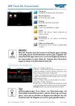
Für die Verbrauchsoptimierung der Chemikalie Chlor, steht 
ein  zweiter  Parametersatz  zur  Verfügung.  Ein  reduzierter 
Sollwert reduziert den Verbrauch an Desinfektionsmittel. 


Da der Nachtbetrieb nur bei einer vernünftigen Wasserqua-
lität eingeleitet werden soll, wird für die Redox-Spannung eine 
Schaltschwelle vorgegeben. 
Nur wenn der Istwert ≥ dem Schwellwert ist, geht der Regler 
in der Nachtbetrieb. 
Sinkt während des Nachtbetriebs die Redox-Spannung unter 
die Schaltschwelle, so wird der Nachtbetrieb beendet 


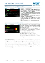
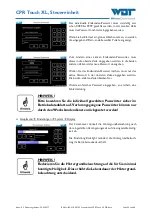
Die  Abbildung  zeigt graphisch  die eingestellten  Schaltzeiten 
für den ECO-Betrieb. 
Die  grünen  Balken  zeigen  die  eingestellten  Zeitblöcke.  Zu-
sätzlich zeigt der grüne Hacken, dass die Schaltzeiten für die-
sen Tag auch aktiv wirken. 
 
Der  rote  Balken  zeigt  zwar  einen  eingestellten  Zeitblock, 
aber der Tag ist deaktiviert. 


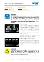
Es  stehen  für  jeden  Tag  4  Zeitblöcke  zur  Verfügung.  Die 
Zeiten können zwischen 00:00 bis 24:00 gewählt werden. 
Der Doppelpunkt muss mit eingegeben werden!  
Tagesübergreifende  Zeiten  müssen  in  zwei  Blöcken  an 
beiden Tagen eingegeben werden. 

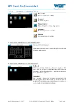
Beispiel:  

Ein  gewünschter  Nachtbetrieb  zwischen  Mo  21:00  bis  Di 
06:00 

Nötige Einstellungen: Mo 21:00 – 24:00 und Di 00:00 bis 
06:00   


Summary of Contents for Granudos 45/100-Touch

Page 1: ... for GRANUDOS 45 100 CPR Touch XL Operating instructions for the CPR Touch XL Measuring and control unit no BA MR 001 GRANUDOS 45 100 Touch Operating instructions for the Granudos Touch Control unit no BA SW 010 GRANUDOS 45 100 S5 Operating instructions for the Granudos Touch Control unit no BA SW 014 ...

Page 2: ...4 Technical data 20 3 4 1 Requirements for the calcium hypochlorite granulate 22 3 5 Transport storage 22 4 Installation 23 4 1 Select the installation site 23 4 2 Installation instructions installation suggestion 23 4 3 Mechanical installation 25 4 3 1 Installation of the GRANUDOS 45 100 dosing system 25 4 3 2 Installation of the buffertank option with without protective tub 25 4 4 Hydraulic inst...

Page 3: ...the GRANUDOS 45 100 dosing device 50 8 3 Buffertank optional 50 8 4 Disposal of used parts and operating materials 50 9 Documents 51 9 1 Declaration of conformity 51 9 2 Wiring diagrams 52 9 3 Commissioning protocol 53 9 4 Operation data sheet 54 9 5 Maintenance protocol 55 9 6 Spare parts list wear parts list consumables 56 10 Appendices 58 Imprint All rights reserved Copyright by WDT Werner Dosi...

Page 4: ...Control unit no BA SW 010 for GRANUDOS S5 GRANUDOS S5 Control Unit no BA SW 014 1 2 Target group Only our authorised partners and people who have been trained in the functioning of the device are permitted to work on the device provided that they have read and understood these operating instructions Electrical connection work may only be carried out by appropriately trained specialists 1 3 Symbols...

Page 5: ...onents that may be damaged by electrostatic discharges The generally accepted safety precautions for ESD sensitive devices must be observed when handling the devices Tip A Tip denotes information that may result in improvements in the operating process Mandatory sign Use face protection Mandatory sign Use protective gloves In accordance with DIN EN 374 Mandatory sign Use protective apron Mandatory...

Page 6: ...uires an invoice for each delivery including warranty services When returning a defective component upon review you will receive a corresponding credit if applicable We request a return within 14 days The costs for subsequent damages and for the processing of warranty claims are excluded There are no warranty claims for damages caused by frost water and electrical overvoltage or by improper handli...

Page 7: ... risks to humans and the environment In the event of an emergency when dealing with chemicals you can also contact the Emergency Poison Centre Emergency number Munich Emergency Poison Centre or any other Poison Centre Phone 49 89 19240 Excerpt from the Accident Prevention Regulations GUV V D 5 Installation rooms for chlorination systems and storage rooms Section 3a 1 Chlorination systems must be i...

Page 8: ...n working with chemicals and it is essential that personal safety equipment is worn Face protection protective gloves protective apron boots The chlorine granulate and the sulphuric acid must not be mixed with each other or with other chemicals or substances Store the chemicals so that they are not accessible to unauthorised persons When storing chemicals observe the notices in Section 3 5 Storage...

Page 9: ... and the acid needed for neutralisation are dosed in turns with intermittent breaks into the dissolving unit The dosed chemicals are completely dissolved and fed into the piping of the swimming pool water circuit The GRANUDOS 45 100 dosing device is particularly well suited for swimming pools with a water volume between 200 and 1500m The functions of the GRANUDOS 45 100 CPR Touch XL Measuring free...

Page 10: ...er Zeit keine Dosierung auf Hauptbecken Luft Versorgungsdruck min 5 barÜ Steuerventil am Granudos NC NO Durchfluss Regelventil Dosierleitung Steuereinheit CPR mit Messzellenblock GRANUDOS Dosiersystem für Calziumhypochlorit Chlor Säure Zulaufleitung Löse und Messwasser Fliesdruck 0 2 barÜ Sicherheitsabschaltung 1 2 Control unit type CPR with measuring cell block Dosing line Heat exchanger Filter C...

Page 11: ...pe Filter Umwälz pumpe Überlauf becken Zentrale Steuerung Steuerung für Niveauschalter Magnetventil öffnet bei Behälter leer Granudos dosiert mit hoher Dosier leistung bis Behälter voll ca 10 Minuten In dieser Zeit keine Dosierung auf Hauptbecken NO NC GRANUDOS Touch Dosierleitung Zulaufleitung Fließdruck 0 2bar 3 2 3 2 Water withdrawal and dosing connection Sleeve Piping DN 20 Chlorine and pH red...

Page 12: ...t 5 Control unit a For type CPR Touch XL with measuring cell block see separate operating instructions CPR Touch XL Measuring and control unit no BA MR 001 b For type CPR Touch XL without measuring cell block see separate operating instructions GRANUDOS Touch Control unit no BA SW 010 c For type S5 without measuring cell block see separate operating instructions GRANU DOS Touch Control unit no BA ...

Page 13: ...g hopper 23 installed on the chlorine drum and the dosing unit The latter consists of the dosing motor with flange 29 the dosing screw 25 the motor bracket 28 and the heating pipe 26 The heating of the dosing pipe prevents the condensation of water vapour which could lead to a dosing blockage The dosing screw 25 conveys the calcium hypochlorite granulate from the Dosing hopper 23 into the flushing...

Page 14: ...flushing tank 48 Connection socket for the switches 49 Motor for dust extraction not illustrated see Figure 11 50 Fan for dust extraction not illustrated see Figure 11 51 Suction hose for dust extraction not illustrated see Figure 11 52 Connection line for dust extraction not illustrated see Figure 11 In the dissolving unit the dissolving water originating from the filter circuit is separated down...

Page 15: ... that has been pushed upward by the upward flow in the suction pipe drops and the chemical dosing is turned off This ensures that dosing only occurs in vigorously flowing water and the two chemicals cannot meet in the open area At the same time the float control valve 45 blocks the Inlet to the flushing tank in the event of a downtime or malfunction of the device However these measures cannot guar...

Page 16: ...djusted during commissioning to ensure that the pH value of the chlorine solution in the buffertank is 6 8 7 2 The calcium hypochlorite is then completely dissolved The solution is clear for practical purposes and has no strong chlorine smell The solution smells strongly of chlorine and is more corrosive when the pH value is too low The solution is murky and forms sediments or deposits in the buff...

Page 17: ...isplay at minimum alarm level 4 An alarm message is shown on the display at maximum alarm level Contact positions The contacts of the level switches are set as follows when the container is half full Level position Contact Level minimum opened Level minimum alarm opened Level maximum opened Level maximum alarm closed An active carbon filter 61 is screwed on top of the buffertank It is used to clea...

Page 18: ...g if the water is very hard and or has a high pH value and or a high dosing performance is required it is recommended to use hydrochloric acid instead of sulfuric acid to prevent the potential formation of gypsum residue due to high sulphate concentrations in the buffertank optional 3 2 7 Granudos Control unit See operating instructions Measuring and control unit CPR Touch GRANUDOS CPR Touch XL no...

Page 19: ...t EN docx Page 19 of 58 3 3 Identification of device nameplate Enter the data from the nameplate of your device here Field 1 Complete the type identification Field 2 Enter drum type Field 3 Article no Field 4 Serial no Field 5 Enter date of manufacturing Nameplate GRANUDOS 45 100 CPR Touch Nameplate GRANUDOS 45 100 Touch Nameplate GRANUDOS 45 100 S5 ...

Page 20: ...n 0 2barg Between circulation pump and filter or filter and heat exchanger before chemical dosing using the booster pump Flow pressure min 0 2barg Operating data max dosing performance GR 45 GR 100 Chlorine 1 2kg h 1 Acid max 3l h 2 Chlorine 2 4kg h 1 Acid max 3l h 2 Chlorine 1 2kg h 1 Acid max 3l h 2 Chlorine 2 4kg h 1 Acid max 3l h 2 Water flow approx 800 1000l h approx 800 1000l h Filling capac...

Page 21: ...lance Required duct connection At least DN25 Operating pressure Required inlet pressure Counter pressure max 2 5barg min 0 2barg 0 1 5barg depending on inlet pressure Pressureless Water supply Between circulation pump and filter or filter and heat exchanger before chemical dosing using the booster pump Flow pressure min 0 2barg Operating data max dosing performance GR 45 GR 100 Chlorine 1 2kg h 1 ...

Page 22: ... be present when opening the drum Specification Calcium hypochlorite concentration higher than 70 Water insoluble Ca OH 2 CaCO3 less than 4 Water crystal water due to safety higher than 10 Grain size Dust smaller than 0 15 mm 100 mesh smaller than 1 Fraction of coarse particles smaller than 2 5 mm 8 mesh smaller than 5 3 5 Transport storage Please check the devices immediately upon receipt for pot...

Page 23: ...n the device configuration an Internet connection may also be required 5 The operating room must not be used as a recreational space max 2 hours per day consult the locally applicable accident prevention regulations Germany BGR GUV R 108 6 It must be possible to vent and aerate technical areas so that hazardous substances do not occur in health hazardous concentrations from accident prevention reg...

Page 24: ...tion incl space requirements without buffertank Dosiergerät GR45 100 CPR Bedien Arbeitsbereich 520 900 800 400 430 1350 200 Figure 13 Suggested installation including space requirements with buffertank Dosiergerät GR45 100 CPR XL Bedien Arbeitsbereich Pufferbehälter optional 520 500 800 100 900 800 430 200 GR45 100 dosing device Operation and working area GR45 100 dosing device Operation and worki...

Page 25: ...rance for operating and servicing the device ATTENTION The GRANUDOS 45 100 must be attached to the floor using the 3 screws included in the delivery Installation materials Spare part bag with manometer gaskets membranes Maintenance set for dosing motor 2 ball valves d25 with adhesive nipple d25 3 4 Options for acid pump 4 3 2 Installation of the buffertank option with without protective tub Place ...

Page 26: ...5 barÜ Steuerventil am Granudos NC NO Durchfluss Regelventil Dosierleitung Steuereinheit CPR mit Messzellenblock GRANUDOS Dosiersystem für Calziumhypochlorit Chlor Säure Zulaufleitung Löse und Messwasser Fliesdruck 0 2 barÜ Sicherheitsabschaltung 1 2 Control unit type CPR with measuring cell block Dosing line Heat exchanger Filter Circulating pump Overflow basin Swimming pool Safety shut down Inle...

Page 27: ...Magnetventil öffnet bei Behälter leer Granudos dosiert mit hoher Dosier leistung bis Behälter voll ca 10 Minuten In dieser Zeit keine Dosierung auf Hauptbecken NO NC GRANUDOS Touch Dosierleitung Zulaufleitung Fließdruck 0 2bar 3 2 3 2 Water withdrawal and dosing connection Sleeve Piping DN 20 Chlorine and pH reducer main basin Heat exchanger Circulating pump Auxiliary basin Main basin Controller f...

Page 28: ...xiliary hygiene parameters i e free chlorine pH value and redox voltage The dosed chemicals must reach all areas of the basin within a short time Even under stress the concentrations measured in different areas of the basin must be approximately the same Water withdrawal A partial flow of the dissolving water is used as measuring water GRANUDOS Touch does not have a measuring water device this has...

Page 29: ...thdrawal at least 80cm below the upper edge of the water The flow pressure at the GRANUDOS Inlet must be at least 0 2barg Install the GRANUDOS 45 100 a short distance below the level of the withdrawal point The height difference between the GRANUDOS and the water surface should be at least 2m Avoid a rising and falling of the Inlet line in the piping to the GRANUDOS 45 100 This can lead to the for...

Page 30: ...ntration thick walled pipes in PVC PN16 must be used At a minimum the piping of the dosing lines must be executed in the dimension d25x2 8mm in PVC PN16 thick walled For longer dosing lines above approx 15m it is recommended to use the dimension d32x3 6mm in PVC PN16 thick walled due to the potentially higher pressure loss Install the dosing line from the GRANUDOS outlet to the injection point Mea...

Page 31: ...er to open the display lid or the small connection space cover the side lid lugs must be gently lifted outwards from the main casing The display lid can then be pulled forward The upper lid lugs run in guide grooves up to the front lock in position Afterwards the display lid is raised The display lid can be supported on the main casing using a standing bracket so that it remains raised for work on...

Page 32: ...ENTION Please pay attention to the spatial separation between energy and signal lines when inserting additional lines The crossing of energy and signal lines must be avoided Upon completion of the work the casing must be properly closed again The device is equipped with a temperature control This temperature control can be used to regulate the basin water temperature If the basin is heated by mean...

Page 33: ...ered with defined factory settings You can find the setting values in the operation data sheet in Section 9 4 ATTENTION During the installation of the piping and the electrical system foreign bodies may have fallen into the flushing unit which could lead to potential faults in the float valve or the suction pipe of the flow switch Remove foreign bodies 5 2 Commissioning Prior to starting the commi...

Page 34: ...e reverse sequence Plug the safety plug in a corresponding socket 5 2 2 Prepare acid dosing for operation PROTECTIVE CLOTHING Personal safety equipment must be put on before starting work with chemicals Protective gloves apron face protection boots The specifications for each chemical listed in the safety data sheets must be observed Connect change acid canister Toxic fumes may occur when handling...

Page 35: ...does not fit on chlorine drums by other manufacturers If a dosing head is improperly installed on a different drum it may detach from the drum during turning causing the chlorine granulate to drop to the ground The removal of the chlorine is unpleasant and time consuming This circumstance should be taken into account when purchasing the chlorine The chlorine granulate and the acid must not be mixe...

Page 36: ...ol unit no BA MR 001 with measuring cell block b For type CPR Touch XL without measuring cell block see separate operating instructions GRANUDOS Touch Control unit no BA SW 010 c For type S5 without measuring cell block see separate operating instructions GRANU DOS Touch Control unit no BA SW 014 6 Nameplate on the right side of the upright pipe covered 7 Chlorine drum 8 Tension bands 9 Safety bel...

Page 37: ...ce so that it is leaning against the posterior tracks and the lower spacers and the holding rod engages with the drum s cross ribs 7 Next pull the tension bands around the drum and close the tension lever The tension lever must be tightly closed however do not use excessive force when turning the tension lever The length of the tension band must be adjusted correspondingly at the screw ends 8 Inse...

Page 38: ... measuring cup if present 6 Place and screw the dosing hopper on the drum so that the drum s recessed grips are oriented laterally and the control cable is pointing backward 7 Lift the drum with the dosing hopper onto the turning device ATTENTION The sloped sides of the hopper hood must point forward and back otherwise the retaining ring does not fit See illustration Watch the dosing hopper s cont...

Page 39: ... vented To do so observe the prefilter d75 If the filter s water level shows a significant drop when the pump is switched on turn off the GRANUDOS open the venting screw on top of the filter and allow water to flow back into the filter before switching the machine back on If necessary repeat the process several times until the filter remains full a few air bubbles in the upper filter area are inco...

Page 40: ...witching body is not clearly pushed upward an orifice with a larger bore is required or the orifice must be removed entirely An orifice with 6mm is installed by the factory orifices with 5 5mm and 7mm are available in the enclosed spare parts bag Overview dissolving unit The dissolving unit consists of 31 Dirt filter d75mm 32 Outflow ball valve for booster water 33 Connection for manometer 34 No c...

Page 41: ...ressure too low appears The GRANUDOS dosing device stops Now turn the adjustment know 0 25bar to the left and acknowledge the alarm message The dosing device will start up again Now the dosing device will throw a fault at a pressure drop of 0 25bar A switching point of 1 5barg is factory set 5 2 6 Setting the water level in the flushing tank The water lever in the flushing tank can be changed by s...

Page 42: ...g and control unit CPR Touch XL no BA MR 001 Operating instruction Control unit GRANUDOS Touch no BA SW 010 Operating instruction Control unit GRANUDOS S5 no BA SW 014 6 2 Replenish consumables PROTECTIVE CLOTHING Personal safety equipment must be used when handling chemicals Tight sealing goggles protective gloves apron face protection boots The safety data sheets for each chemical must be observ...

Page 43: ... the filter and remove the filter from its bracket Pull out the filter insert under running water Clean the filter hood and the filter insert under running water 7 1 2 Replacing the dosing screw and the dust gasket ATTENTION The protective cover must be removed prior to any work described in Section 7 1 2 Deinstallation installation of the protective cover 1 Push the dust protection pipe 12 downwa...

Page 44: ... chlorine grains d Clean the screw Is the chlorine granulate inside the screw heavily solidified or does the granulate easily scatter from the screw when this is pulled out e If the granulate is solidified it may be too moist or have an excessive dust content It is also possible that the screw is too worn and the granulate is no longer conveyed properly 7 1 2 2 Maintenance of the dosing motor a Di...

Page 45: ...within a short time and can no longer be unscrewed If the dosing screw or the motor must be replaced again at a later time both parts would have to be replaced together 7 1 2 3 Individually replace the dosing motor a Entirely unscrew the threaded pin from the old dosing screw and insert a new threaded pin b Clean the front surface of the old dosing screw s adapter and cover with silicon grease c O...

Page 46: ...that the threaded pin is located on the flat part of the motor shaft press firmly against motor and tighten the threaded pin d Push the motor with dosing screw back into the cleaned bracket tighten the flange not too tight and push the protective covers on the screw heads 7 1 3 Injector with flow switch Overview flow switch 81 Flow switch with LED 82 Union nut for flow switch 83 Viton hose to the ...

Page 47: ...nion nut for float assembly 104 Adjustment screw for water level 105 Float 250ml 106 Float valve body Overview Tappet for float valve 108 Membrane piston 109 Sealing membrane 110 Valve cone with O ring gasket Replace the sealing membrane a Unscrew the union nut 103 and remove the upper part of the float valve b Remove the inner membrane valve assembly 108 110 pull the valve cone from the membrane ...

Page 48: ...oes not react to the adjustment potentiometer or if the adjustment screw has been destroyed a new switch must be installed Adjust the empty switch drum rotated upward Turn the adjustment screw to the right until the switch LED is illuminated then carefully turn it back until the switch LED goes out followed by an additional 10 turn The Disinfection Level fault is displayed at the controller After ...

Page 49: ...it This does not require the disassembly of the dust extraction 7 2 Trouble shooting Tip Faults are indicated in the display in the IN and OUT list by the appropriate symbol See also separate operating instructions for GRANUDOS CPR Touch XL CPR Touch XL Measuring and control unit no BA MR 001 with measuring cell block in Section 7 3 for GRANUDOS Touch GRANUDOS Touch Control unit no BA SW 010 in Se...

Page 50: ...der to relieve the dosing hose 8 Thoroughly clean all parts of the GRANUDOS 45 100 9 If there is a risk of frost drain all of the water conveying parts in particular do not forget the suction pipe and the pump 10 Deactivate the dosing device at the main switch Or in very cold and moist rooms keep the dosing device activated to prevent potential condensation in the controller casing Also observe Se...

Page 51: ...s 45 100 CPR Touch XL Touch S5 Dosing unit Index 02 Date modified 06 06 2019 OI No BA SW 003 02 Granudos 45 100 CPR Touch Touch S5 Dosiereinheit EN docx Page 51 of 58 9 Documents 9 1 Declaration of conformity ...

Page 52: ...e devices can be found in the respective operating instructions for the control unit for GRANUDOS CPR Touch XL CPR Touch XL Measuring and control unit no BA MR 001 in Section 9 2 for GRANUDOS Touch GRANUDOS Touch Control unit no BA SW 010 in Section 9 2 for GRANUDOS S5 GRANUDOS S5 Control Unit no BA SW 014 in Section 9 2 The special wiring diagrams attuned to the optimal furnishing of the dosing d...

Page 53: ...t Index 02 Date modified 06 06 2019 OI No BA SW 003 02 Granudos 45 100 CPR Touch Touch S5 Dosiereinheit EN docx Page 53 of 58 9 3 Commissioning protocol The commissioning protocol for the respective device is located in the accompanying documentation ...

Page 54: ... Dosiereinheit EN docx Page 54 of 58 9 4 Operation data sheet See operating instructions Control unit for GRANUDOS CPR Touch XL CPR Touch XL Measuring and control unit no BA MR 001 in Section 9 4 for GRANUDOS Touch GRANUDOS Touch Control unit no BA SW 010 in Section 9 4 for GRANUDOS S5 GRANUDOS S5 Control Unit no BA SW 014 in Section 9 4 ...

Page 55: ...nit Index 02 Date modified 06 06 2019 OI No BA SW 003 02 Granudos 45 100 CPR Touch Touch S5 Dosiereinheit EN docx Page 55 of 58 9 5 Maintenance protocol The maintenance protocol for the respective device is located in the accompanying documentation ...

Page 56: ...Tension band GR PAK 11500 0 Safety belt GR 45 complete set 17978 0 Safety belt GR45 HTH25 Bü40 Tri40 complete set 17979 Flushing tank 0 Flushing tank GR45 PE processed with NIG 13127 1 0 Flushing pipe swirler GR 45 100 25078 0 Suction connection to the flushing tank PE GR45 100 3 4 25052 0 NIG 2P 3 8 GR PAK 0 35m 10496 Acid dosing 0 Acid pump Sa complete 11628 0 Gear motor to peristaltic pump Sa 1...

Page 57: ... 0 7m 25671 0 Hose to suction pipe 10x2x190Vi GR 11565 1 Injector 0 Injector Ti 1 2 GR PAK HT complete 24997 0 Orifice set for injector 11594 0 Connecting angle injector cyclone 12308 Cyclone 3 Dissolving cyclone GR 45 11612 1 2 Dissolving cyclone for GPL and PB 45 100 11613 1 2 IR sensor 18x1 GPL PAK PB complete 11609 Maintenance set 0 X Gaskets fuses maintenance protocol 12631 Dust extraction 0 ...

Page 58: ...uch XL Touch S5 Dosing unit Index 02 Date modified 06 06 2019 OI No BA SW 003 02 Granudos 45 100 CPR Touch Touch S5 Dosiereinheit EN docx Page 58 of 58 10 Appendices Commissioning protocol Maintenance protocol Personal notes ...

Page 59: ...device stopped fault display 1 7 Adjust the pressure switch 41 1 8 Check flow switch Outlet ball valve closed dosing stopped fault indication 1 9 Set the water level in the rinsing tray 1 10 Check level switch Switching body high dosing stopped fault indication 1 11 Check the level switch Switching body low device stopped fault indication 1 12 Check the floater valve function flow reacts gently 2 ...

Page 60: ...ck see operating instructions part 2 MR001 for CPR Touch XL 6 1 Fill in cleaning beads 6 2 Insert electrodes 6 3 Open the ball valve at the measuring cell feed set the measuring cell flow 6 4 Adjust the regulation parameters 7 Other 7 1 Clean the GRANUDOS system 7 2 Discuss the operating instructions and hand them over Other comments Commissioning and instruction performed by Persons instructed Si...

Page 61: ... 4 Replace the float valve membrane and cone seal 12 1 5 Check and adjust the float valve function 6 1 6 Replace the hose to the suction pipe 12 1 7 Check the pump impeller and lid only for Calpeda pumps 12 1 8 Check pump floating ring seal for tightness 6 1 9 Check pump roller bearings for noises 6 1 10 Clean the dirt filter 3 1 11 Replace all O rings 12 1 12 Check nozzle diameter diffuser 6 mm u...

Page 62: ...DPD1 measurement adjust free chlorine 12 7 3 pH measurement adjust the pH electrode 12 7 4 Adjust the reference counter electrode 12 7 5 Chlorine electrode replace seal set 12 7 6 Replace redox electrode seal set 12 7 7 Replace flow controller maintenance set 12 7 8 Replace the membrane of the pressure control valve 2 12 8 Other work 8 1 Thoroughly clean the dosing system 1 8 2 Check dosing line f...

Page 63: ...sing stopped fault indication 1 8 Set the water level in the rinsing tray 1 9 Check level switch Switching body high dosing stopped fault indication 1 10 Check the level switch Switching body low device stopped fault indication 1 11 Check the floater valve function flow reacts gently 2 Chlorine dosing technology 2 1 Heating function Dosing pipe warm 2 2 Empty switch function Drum turning fault ind...

Page 64: ...ätsmanagement ISO 9001 MS Originale Formuale Prüfbericht etc WDT Inbetriebnahmeprotokoll IP WDT IP 48 GR 45 100 Touch EN FO 00 doc Page 2 of 2 Other comments Commissioning and instruction performed by Persons instructed Signature of commissioner Countersigned by operator ...

Page 65: ...lace the float valve membrane and cone seal 12 1 5 Check and adjust the float valve function 6 1 6 Replace the hose to the suction pipe 12 1 7 Check the pump impeller and lid only for Calpeda pumps 12 1 8 Check pump floating ring seal for tightness 6 1 9 Check pump roller bearings for noises 6 1 10 Clean the dirt filter 3 1 11 Replace all O rings 12 1 12 Check nozzle diameter diffuser 6 mm use 6mm...

Page 66: ...k 6 Control 6 1 Check all inputs 12 6 2 Check all outputs 12 6 3 Check parameter settings and correct it if required 12 7 Other work 7 1 Thoroughly clean the dosing system 1 7 2 Check dosing line for strength and wall thickness 12 8 Maintenance work at each drum exchange 8 1 Clean the solution pipe for pollution F 8 2 Clean dosing hopper from incrustations F 8 3 Test chlorine and acid dosing F 8 4...

Page 67: ...ed dosing stopped fault indication 1 8 Set the water level in the rinsing tray 1 9 Check level switch Switching body high dosing stopped fault indication 1 10 Check the level switch Switching body low device stopped fault indication 1 11 Check the floater valve function flow reacts gently 2 Chlorine dosing technology 2 1 Heating function Dosing pipe warm 2 2 Empty switch function Drum turning faul...

Page 68: ...ätsmanagement ISO 9001 MS Originale Formuale Prüfbericht etc WDT Inbetriebnahmeprotokoll IP WDT IP 60 GR 45 100 S5 EN FO 00 doc Page 2 of 2 Other comments Commissioning and instruction performed by Persons instructed Signature of commissioner Countersigned by operator ...

Page 69: ...ce the float valve membrane and cone seal 12 1 5 Check and adjust the float valve function 6 1 6 Replace the hose to the suction pipe 12 1 7 Check the pump impeller and lid only for Calpeda pumps 12 1 8 Check pump floating ring seal for tightness 6 1 9 Check pump roller bearings for noises 6 1 10 Clean the dirt filter 3 1 11 Replace all O rings 12 1 12 Check nozzle diameter diffuser 6 mm use 6mm d...

Page 70: ... Control 6 1 Check all inputs 12 6 2 Check all outputs 12 6 3 Check parameter settings and correct it if required 12 7 Other work 7 1 Thoroughly clean the dosing system 1 7 2 Check dosing line for strength and wall thickness 12 8 Maintenance work at each drum exchange 8 1 Clean the solution pipe for pollution F 8 2 Clean dosing hopper from incrustations F 8 3 Test chlorine and acid dosing F 8 4 Ta...

Page 71: ... Messzellenblock BA Teil 2 für Steuereinheit Messtechnik für pH Wert freies Chlor Redox Spannung und Temperatur Teil 2 zur BA der Dosiergeräte Granudos 10 CPR Touch XL Nr BA SW 002 Granudos 45 100 CPR Touch XL Nr BA SW 003 CPR Touch XL 2S Nr BA SW 004 Art Nr Sprache DE ...

Page 72: ...d 14 3 4 Technische Daten 15 3 5 Transport Lagerung 16 4 Montage 17 4 1 Aufstellungsort auswählen 17 4 2 Montagehinweise Einbauvorschlag 17 4 3 Montage mechanisch 17 4 4 Montage hydraulisch 17 4 5 Montage elektrisch 17 5 Inbetriebnahme 18 5 1 Inbetriebnahme Anmerkungen 18 5 2 Inbetriebnahmearbeiten 18 5 2 1 Reinigungsperlen einfüllen 18 5 2 2 pH und Kombi Elektroden mit Glasschaft einsetzen 19 5 2...

Page 73: ...teil mit Anschluss an die IO Platine für Gerät GR 10 CPR 56 9 2 6 Klemmplan I O Platine GRD 7 für Gerät GR 10 CPR 57 9 2 7 Klemmplan Netzteil mit Anschluss an die I O Platine für Gerät GR 45 100 CPR 58 9 2 8 Klemmplan I O Platine GRD 7 für Gerät GR 45 100 CPR 59 9 2 9 Klemmplan Puffertank GRD 7 für die Geräte GR 10 CPR und GR 45 100 CPR 60 9 2 10 Klemmplan Messplatte für die Geräte GR 10 CPR und G...

Page 74: ...e An der Anlage dürfen ausschließlich unsere autorisierten Partner und die in die Gerätefunktionen eingewiesenen Personen arbeiten wenn sie diese Betriebsanleitung gelesen und verstanden haben Die elektrotechnischen Anschlussarbeiten dürfen nur durch entsprechend ausgebildete Fachkräfte ausgeführt werden 1 3 Verwendete Symbole In diesem Dokument werden die folgenden Arten von Sicherheitshinweisen ...

Page 75: ...tladung beschädigt werden können Bei der Handhabung der Geräte sind die allgemein bekannten Vorsichtsmaß nahmen für ESD empfindliche Geräte einzuhalten HINWEIS Ein Hinweis kennzeichnet Informationen deren Nichtbeachtung zu Betriebsstörungen führen können Tipp Ein Tipp kennzeichnet Informationen die zur Verbesserung des Betriebsablaufes führen können Gebotsschild Gesichtsschutz verwenden Gebotsschi...

Page 76: ... Prüfung ggf eine entsprechende Gutschrift Wir bitten um Rücksendung innerhalb von 14 Tagen Kosten für Folgeschäden und Kosten für die Abwicklung von Gewährleistungsansprüchen sind ausgeschlossen Gewährleistungsansprüche bestehen nicht bei Schäden welche durch Frost Wasser und elektrischer Überspannung oder durch unsachgemäße Behandlung entstanden sind Tipp Zur Wahrung von Gewährleistungsansprüche...

Page 77: ...child genaue Gerätebezeichnung Geräteseriennummer Baujahr Für technische Supportanfragen benötigen wir zudem folgende Daten Diese finden Sie im Menüpunkt Menue Service Info aktuelle Version der Firmware aktuelle Version der Hardware Bei Problemen mit den Messwerten benötigen wir immer alle aktuellen Messwerte So helfen Sie uns die Störung schneller beurteilen zu können Dadurch können wir Ihnen ein...

Page 78: ... Personen darauf zugreifen können Auch für die Sicherheit der Ver bindungen über das Internet bzw WLAN ist der Betreiber selbst bzw die von ihm be auftragte Person zuständig 2 2 1 Umgang mit Chemikalien Gefahren für Mensch und Umwelt Bei Notfällen im Umgang mit Chemikalien können sie sich an die Giftnotruf Zentrale wenden Notrufnummer Giftnotruf München oder jedes andere Giftzentrum Telefon 49 89 ...

Page 79: ...iff Begriffe Fernzugriff externe Nutzung Bedienung des Gerätes über ein Netzwerk z B Inter net LAN W LAN Systeminhaber Endnutzer Endkunde Betreiber auch juristische Person Servicepartner Händler Inverkehrbringer Nutzer jeder der die Möglichkeit des Fernzugriffs besitzt z B Servicepartner EDV Dienstleister Systeminhaber Hersteller Hersteller Hersteller des Gerätes Wir als Hersteller des Gerätes wei...

Page 80: ...n ein Fernzugriff nicht mehr erfolgen soll Passwörter müssen vertraulich behandelt werden und Komplexitätsvoraussetzungen er füllen Diese Voraussetzungen finden Sie in der Betriebs und Montageanleitung des Ge rätes Wir weisen Sie darauf hin dass Sie mit der Aktivierung des Fernzugriffs die sicherheits technischen Anforderungen nach aktuellem Stand der Technik einhalten müssen Dies gilt ins Besonde...

Page 81: ...r Mess und Regelaufgaben bei der Schwimmbadwasseraufbereitung bestimmt Sie wird für die folgenden 3 Dosiergeräte eingesetzt GRANUDOS 10 CPR Touch XL GRANUDOS 45 100 CPR Touch XL CPR Touch XL 2S Die Steuerung besitzt folgende Hauptfunktionen Regulierung des pH Wertes mit Schlauchpumpe direkt aus dem Liefer Kanister Regulierung der Desinfektionsdosierung mit Förderschnecke Typ Granudos oder Schlauch...

Page 82: ...te gewährleistet Es werden somit eventuelle Ausführungsfehler seitens des Montagepersonals weitestgehend vermieden Zum Transport wurden vom Werk aus die beiden Elektroden mit Glasschaft aus der Mess zelle ausgebaut und in einem Verpackungskarton mitgeliefert Um eine Deformation der Dosierschläuche bei längerer Lagerung zu vermeiden sind die Rollenträger der Schlauch pumpen von der Motorwelle abgez...

Page 83: ...warz 6 Durchflussregelventil 7 PMMA Messzellenblock 8 Prüfwasserhahn 9 Vorfilter bei 2S optional zur Wandmontage 10 Redox Elektrode 11 Chlorelektrode 12 Messwasserzulauf 13 Messwasserrücklauf 14 Redox Prüfzylinder 15 2 Dosierpumpen Sa bei Granudos 45 100 nicht im Bild zu sehen 16 Pufferlösungen und Elektrode Reiniger 17 Dosierventile nur bei 2S 18 Sauggarnituren nicht im Bild zu sehen Abbildung 3 ...

Page 84: ...akte Messzellenblock 7 besteht aus Acrylglas und dient zur Aufnahme der Elektroden Dosierventile Reinigungsperlen und des Probeentnahmehahns Es wird der Durchfluss reguliert und das Messwasser rückgeführt 3 3 Identifikation des Gerätes Typenschild Für Ersatzteilbestellungen und Problembehandlungen ist es sinnvoll die Geräteseriennum mer und die Firmwareversion zu kennen Die Geräteseriennummer befi...

Page 85: ... Luftfeuchtigkeit Technikraum 0 C bis 40 C 5 C bis 35 C max 80 nicht kondensierend 0 C bis 40 C 5 C bis 35 C max 80 nicht kondensierend Konzentration hypochlorige Säure max 0 2 Be und Entlüftung des Raumes Nach DIN 19643 Nach DIN 19643 Material Gehäuse PS Messwasserleitung PE Dosierleitungen PTFE Gehäuse PS Messwasserleitung PE Firmwareversion Hardwareversion GRANUDOS 45 100 CPR Steuerungs technik...

Page 86: ...turen beschädigt werden Frosteinwirkung bei Transport und Lage rung verhindern Anlagen und Geräte nicht neben Gegenständen mit starker Wärmeabstrahlung oder direkter Sonneneinstrahlung lagern Das Gerät darf nur in der Originalverpackung transportiert und gelagert werden Dabei ist auf sorgsame Behandlung zu achten Lagerung von Chemikalien HINWEIS Es sind die Sicherheitsdatenblätter der Chemikalienl...

Page 87: ...chenden Dosiergerät 4 2 Montagehinweise Einbauvorschlag Siehe Betriebsanleitung Teil 1 Dosiertechnik zum entsprechenden Dosiergerät 4 3 Montage mechanisch Siehe Betriebsanleitung Teil 1 Dosiertechnik zum entsprechenden Dosiergerät 4 4 Montage hydraulisch Siehe Betriebsanleitung Teil 1 Dosiertechnik zum entsprechenden Dosiergerät 4 5 Montage elektrisch Siehe Betriebsanleitung Teil 1 Dosiertechnik z...

Page 88: ...4 HINWEIS Achten Sie auf festen Sitz aller Schlauchverschraubungen der Messwasserleitungen Kontrollieren Sie alle Verschraubungen am Gerät und an den beiden Messwasserkugelhähnen Kunststoff Verschraubungen sind nur handfest anzuziehen 5 2 Inbetriebnahmearbeiten Führen Sie die Inbetriebnahmearbeiten in der aufgeführten Reihenfolge durch 5 2 1 Reinigungsperlen einfüllen Die mitgelieferten blauen Rei...

Page 89: ...nd kann die Messwasserzufuhr geöffnet werden Am Durchfluss regelventil Pos 6 wird die Durchflussmenge eingestellt Der Durchflussschwebekörper Pos 2 muss nach oben gedrückt werden um die Dosierung frei zu geben Die Reini gungsperlen müssen auf den Metalloberflächen stark rotieren Wenn die Reinigungsperlen abheben ist Durchfluss zu hoch und die Reinigungswirkung nicht gewährleistet 5 2 4 Die Regelpa...

Page 90: ... oder eines Zahlenwertes wird dies zur Parametrierung aktiviert Die Justiermenüs sind zusätzlich mit textgeführten Anweisungen versehen 6 2 1 Betriebsanzeige Display auto mode Die mikroprozessorgestützte Steuerung des CPR Touch XL ist mittels eines 7 Touch Displays einfach und übersichtlich zu bedienen Im Startbildschirm werden die Betriebszustände und Störungen direkt angezeigt siehe Abbildung 6 ...

Page 91: ...uereinheit an Die OUT Liste zeigt die aktiven Ausgangssignale der Steuereinheit an Erklärung der Symbole Die Symbole sind abhängig von der eingesetzten Firmware sprich Gerätevariante IN Liste allgemein rot Niveau pH Gebinde für pH Regulierung leer gelb Niveau Desinfektion Gebinde für Desinfektionsmittel leer blau Niveau Flockung Gebinde Flockungsmittel leer Schlauchbruch an einer der eingebauten S...

Page 92: ...re gibt es in unterschiedlichen Gerätevarianten Je nach Funktionsumfang werden in den einzelnen Menüpunkten mehr oder weniger Icons eingeblendet Nachfolgende Symbole sind nur bei der Gerätevariante GRANUDOS aktiv IN Liste nur für Granudos Der Druck an der GRANUDOS Treibwasserpumpe ist zu gering Die Treibwasserpumpe wird gestoppt Das Niveau in der GRANUDOS Spülwanne ist zu gering Die Treibwasserpum...

Page 93: ...ch Der optische Sensor am Zyklon hat während der Pufferbefüllung kein Chlor erkannt Die Befüllung wurde deaktiviert Die Pufferbefüllung wurde vom System abgebrochen Die Befüllung erfolgte zu langsam OUT Liste optional Ausführung mit Puffertank Die Befüllung des Puffertanks ist aktiv Die Funktionstasten am Startbildschirm Dosierverzögerung manuell abbrechen Dosierung startet Dosierung für Servicear...

Page 94: ...end der kein Dosierausgang angesteuert wird Softwarealarme werden während dieser Zeit unterdrückt Die Dosierverzögerung muss so hoch gewählt werden dass nach einem Start der Filteranlage gewährleistet ist dass aktuelles Beckenwasser durch die Messzelle fließt Mit kann die Dosierverzögerung abgebrochen und das Gerät in den Automatikbetrieb gesetzt werden 6 2 5 Alarm Ist ein Alarmeingetreten so wird...

Page 95: ...itüberwachungsalarm wird mit signalisiert Diese Störung wird nur durch einen Geräteneustart bzw eine manuelle Quittierung zurückgesetzt 6 2 7 Automatic Redox Regelung Notprogramm Im Falle eines nicht behebbaren Defektes in der Messung freies Chlor z B Elektrodenbruch kann für einen temporären Betrieb die Desinfektionsdosierung über die Notfunktion der Redox Regelung erfolgen Wird dieser Betriebsmo...

Page 96: ...sworteingabe Im Auslieferungszustand ist kein Passwort vergeben Log Zur Abfrage der Ereignisse und Datenlogging Justieren Justieren der pH Redox Elektrode DPD1 Justierung 6 2 9 Hauptmenü Einstellungen Übersicht Im Menü Einstellungen nehmen sie die gewünschten Einstellungen für das Dosiergerät vor Mit den seitlichen weißen Pfeiltasten können sie zum nächsten Bildschirmmenü blättern pH Regelparamete...

Page 97: ...tes vorgenommen werden Nach der Vergabe eines Passwortes tragen sie dieses in das Betriebsdatenblatt ein Hauptmenü Einstellungen pH Alarm low unterer Alarmwert P Bereich Die Dosierung arbeitet proportional d h je größer die Differenz zwischen Sollwert und Istwert desto länger ist die Dosierzeit max 8 Sekunden Je kleiner der Regelbereich gewählt wird desto schneller reagiert der Messwert und desto ...

Page 98: ...rbrauch des Pools Gerade bei geringeren Wasserinhalten ist es sehr wichtig die Dosierleistung anzupassen Die nötige Dosierleistung ist von mehreren Faktoren wie z B Beckenvolumen Standort Nutzungsart und natürlich der Frequentierung der Badegäste abhängig pH Dosierzeit der Säure in Sekunden Desinfektion Dosierzeit Chlor in Sekunden Zykluszeit Länge des Gesamtzyklus in Sekunden Handdosierung Wechse...

Page 99: ...efektes in der Messtechnik z B Elektrodenbruch not wendig sein Für einen begrenzten Zeitraum kann sowohl die Desinfektionsdosierung als auch die Dosierung der pH Wert Regulierung über die Notfunktion Handbetrieb erfolgen Nach der Aktivierung der Handdossierung ändert sich die Ansicht im Startbildschirm Bei Granudos Anstelle der Messwerte wird das Fließbild eines Dosiergerätes mit Puffertank eingeb...

Page 100: ...h je größer die Differenz zwischen Sollwert und Istwert desto länger ist die Dosierzeit max 15 Sekunden Je kleiner der Regelbereich gewählt wird desto schneller reagiert der Messwert und desto leichter kann es zu einer Überdosierung kommen Sollwert diesen Wert versucht das Gerät zu erreichen Alarm high oberer Alarmwert Dostime Limit wird der Regelbereich nicht innerhalb drei x der eingestellten Ze...

Page 101: ...ereinheit überwacht Hauptmenü Einstellungen ECO Betrieb Nachtbetrieb DIN Kontakt Die Funktion ECO dient einem energiekosten und verbrauchsoptimierten Betrieb Es gibt zwei Betriebsarten den Master und den Slave Betrieb Betriebsart Master In der Betriebsart Master geht der Regler gemäß den im Menü Zeiten gewählten Zeitblöcke in den Nachtbetrieb Betriebsart Slave In der Betriebsart Slave leitet ein S...

Page 102: ...bs die Redox Spannung unter die Schaltschwelle so wird der Nachtbetrieb beendet Die Abbildung zeigt graphisch die eingestellten Schaltzeiten für den ECO Betrieb Die grünen Balken zeigen die eingestellten Zeitblöcke Zu sätzlich zeigt der grüne Hacken dass die Schaltzeiten für die sen Tag auch aktiv wirken Der rote Balken zeigt zwar einen eingestellten Zeitblock aber der Tag ist deaktiviert Es stehe...

Page 103: ...stem Datum Zeit Datum und Uhrzeit anpassen Sie können eine automatische Umschaltung von Winter auf Sommerzeit aktivieren b Hauptmenü Einstellungen System Passwort Endkunde Werkseitig ist kein Endkunden Passwort vergeben Wir empfehlen die Vergabe eines Endkunden Passwortes zum Schutz vor unberechtigtem Zugriff Tragen sie das Passwort in das Betriebsdatenblatt ein Techniker 1 Das Techniker 1 Passwor...

Page 104: ...t löschen muss nur das aktive Passwort in der obersten Zeile eingegeben werden Die beiden anderen Zeilen bleiben frei Wurde ein falsches Passwort eingegeben so erschein eine Fehlermeldung HINWEIS Bitte bewahren Sie die individuell gewählten Passwörter sicher im Betriebsdatenblatt auf Verlorengegangene Passwörter können nur durch den Werkskundendienst zurückgesetzt werden c Hauptmenü Einstellungen ...

Page 105: ... von Ihnen gewünschte Bedienersprache Hauptmenü Einstellungen Hochchlorung Dieses Menü erlaubt die Anpassung der Dosierleistungen während einer Hochchlorung Wählen Sie die Dosierleistung so dass die gewünschte Konzentration während der Hochchlorung vorliegt Zur Kontrolle muss die Konzentration mehrmals während der Hochchlorung photometrisch ermittelt werden Hauptmenü Einstellungen Puffertank für G...

Page 106: ...die Stiftleiste SLx und Klemmen Pinx x an denen der Schalter angeschlossen ist Die fünfte Spalte zeigt die Funktion der Schalter NO bzw NC NO normally open bedeutet im Betriebszustand offen und Störungsfall geschlossen NC normally closed bedeutet im Betriebszustand geschlos sen und Störungsfall offen Mit den und Buttons können die Seiten durchgeblättert werden Hauptmenü Service Ausgangstest Der Au...

Page 107: ... Passwort schützt den Regler vor unerlaubtem Zugriff Ohne Passwort sind dann keine Einstellungen Justierungen Ausgangstests etc mehr möglich Die Durchsicht des Menüs und die Einsicht des Datenlogging sind weiterhin möglich Für künftige Änderungen und Justierungen müssen Sie sich unter Login mit dem persönlichen Passwort anmelden Wechselt man auf den Startbildschirm so muss das Passwort erneut eing...

Page 108: ... wird dieser Tag weiß hinterlegt Mit dem ICON Event Log können Sie die Ereignisse des ausgewählten Tages einsehen Hauptmenü Log Data Log Bei aktiviertem Data Log werden die Messwerte jede Minute festgeschrieben Der Verlauf der Messwerte kann tabellarisch oder grafisch dargestellt werden Mit den Pfeiltasten können sie nach oben und unten blättern Hauptmenü Log Export Unter dem Menüpunkt Export könn...

Page 109: ...r pH Elektrode phenolrot Einpunkt Justierung der pH Anzeige DPD1 Justierung der Anzeige freies Chlor mV Redox Justieren der Redox Messung Die Justierungen sind graphisch geführt und mit Hilfstexten versehen Mit der OK Taste werden abgearbeitete Schritte quittiert Hauptmenü Justieren pH Elektrode Führen Sie die Justierung gemäß den Anweisungen durch Am Ende der pH Justierung werden die Messergebnis...

Page 110: ...ierung mit einem Reinigungshinweis beendet Fehlerhinweis Bei einer Nullpunktspannung 61mV wird der Spannungswert rot eingefärbt und die Justierung mit einem Fehlerhinweis verweigert Bei einer Steilheitsspannung 50mV bzw 65mV pH wird der Spannungswert rot eingefärbt und die Justierung mit einem Fehlerhinweis verweigert Wird die Justierung mit einem Fehlerhinweis verweigert so regelt das Gerät mit d...

Page 111: ...der Elektrode keine Besserung bringen so ist der Fehler am Elektrodenkabel bzw Messverstärker zu suchen Hauptmenü Justieren DPD1 freies Chlor Im ersten Schritt der DPD1 Justierung werden drei Abbildungen nacheinander eingeblendet Es wird beispielhaft die Vorgehensweise einer DPD1 Messung mittels einem Photometer und Tablettenmessung dargestellt Die genaue Vorgehensweise entnehmen Sie bitte der Bed...

Page 112: ...e z B 220mV oder 640mV erfolgen Bitte beachten Sie bei einem Abgleich die Temperaturab hängigkeit der Prüflösung Siehe Etikett Am Menüende wird die eingestellte Abweichung als Offset an gezeigt Bei geringen Abweichungen wird die Justierung so fort übernommen Bei Abweichungen größer 41mV wird ein Reinigungshin weis gegeben Bei Abweichungen größer 61mV wird auf einen Aus tausch der pH Elektrode hing...

Page 113: ...Arbeiten an wasserführenden Leitungen schließen sie immer die Ein und Auslassventile Stellen sie einen Eimer unter den Filter Drehen sie die Filterglocke aus der Halterung heraus Ziehen Sie den Filtereinsatz aus der Filterglocke heraus und waschen den Filtereinsatz unter fließendem Wasser Einbau in umgekehrter Reihenfolge HINWEIS Ein verschmutzter Vorfilter kann zu einer Chlorzehrung führen Dies w...

Page 114: ...ktrodensteckkopf sowie auch die des Elektrodensteckers müssen goldig glänzend aussehen und dürfen keine Korrosionen aufweisen HINWEIS Nach jeder Elektrodenreinigung oder nach einem Elektrodentausch ist eine Justierung durchzuführen Die Glaskuppe Sensorteil und das Diaphragma nicht mit den Fingern berühren Die Glaskuppe mit einem sauberen und weichen Tuch abtupfen 7 1 4 Bezugs Gegen Kombielektrode ...

Page 115: ...nter Be rücksichtigung der geltenden Sicherheitsbestimmungen ausgeführt werden Sicherungen im Inneren des Steuergehäuses dürfen nur durch War tungs oder Instandsetzungspersonal gewechselt werden Für Typ GR 10 CPR und 2S Abbildung 8 Steuergehäuse Typ GR 10 CPR und 2S Der Displaydeckel kann für Installations und Servicearbeiten je nach Gerätetyp entweder nach links oder nach rechts geschwenkt werden...

Page 116: ...kel nach unten geschlos sen werden Jetzt müssen die oberen De ckellaschen entriegelt und der Deckel nach hinten auf das Grundgehäuse geschoben werden Um das Gehäuse wieder dicht zu verschließen müssen Sie auf die vier Ge häuseecken einen leichten Druck ausüben Der Gehäusedeckel schließt mit einem leicht hörbaren Klick Bitte vergewissern Sie sich davon dass immer alle Deckellaschen sicher mit den S...

Page 117: ...rschalter defekt 3 Bei neuer Sauglanze die Funktionsrichtung des Schwimmers prüfen 4 Druck minimal ALARM Der Fließdruck an der Treibwas serpumpe ist zu gering Die Dosierung wird gestoppt Die Treibwasserpumpe ist ab geschaltet 1 Zu niedriger Versorgungsdruck 2 Treibwasserpumpe fehlerhaft 3 Druckschalter fehlerhaft 4 Einstellen eines niedrigeren Ansprechdrucks am Druckschalter 5 Niveau Spülwanne min...

Page 118: ...achspülzyklus startet danach stoppt das Dosiergerät die Erzeugung der Chlorlösung 12 Niveau Puffertank minimal ALARM Der untere Steuerschalter zum Starten der Befüllung hat nicht angesprochen Schalterfunktion überprüfen Bei leerem Tank muss der Schaltkontakt geschlossen sein messen an der Klemme Falls offen Schalter oder Klemmkontakt fehlerhaft 13 Niveau Puffertank maximal ALARM oder Alarm Auffang...

Page 119: ...erät stoppt Keine Maßnahme da eine externe Abschaltung erfolgt ist 21 Dosierzeitüberschrei tung ALARM Eine dynamische Dosierzeit wurde überschritten Der ent sprechende Ausgang ist blo ckiert Aus Platzgründen wird keine Unterscheidung der ein zelnen Kanäle vorgenommen Dosierschnecke und Dosierpumpen auf Defekt und Blockierung prüfen Defekt bzw Blockierung beseitigen siehe auch Abschnitt 7 zur entsp...

Page 120: ...zkappe etwa zur Hälfte mit Elektrolyt befüllt und auf den Glasschaft der pH Elektrode bzw der Bezugs Gegen Kombielektrode geschoben Die Einstabmessketten sind bis ca 15 C frostfest bei tieferen Temperaturen müssen diese unbedingt an einem frostsicheren Ort gelagert werden Ist am Installationsort mit Kondensationsfeuchtigkeit zu rechnen so muss zum Schutz der Elektronik das Gerät durchgehend mit Sp...

Page 121: ...triebsanleitung Teil 1 zum entsprechenden Dosiergerät 9 2 Klemmpläne GEFAHR Lebensgefahr durch hohe Spannung Alle elektrischen Arbeiten am Gerät dürfen nur durch ausgebildete Fachkräfte unter Berücksich tigung der geltenden Sicherheitsbestimmungen ausgeführt werden Innere Sicherungen dürfen nur bei unterbrochener und gegen Wi dereinschalten gesicherter Spannung erneuert werden ...

Page 122: ...ldete Fachkräfte unter Berücksich tigung der geltenden Sicherheitsbestimmungen ausgeführt werden Innere Sicherungen dürfen nur bei unterbrochener und gegen wi dereinschalten gesicherter Spannung erneuert werden Die Abbildung zeigt beispielhaft den Anschluss einer 230 Volt Umwälzpumpe für die Beckenwasser erwärmung und den Ausgang Chlor 230 V 50 Hz Sicherungen Stromstärke Sicherungs Art Funktion F1...

Page 123: ...t CPR Touch XL DE docx Seite 53 von 68 9 2 2 Klemmplan I O Board für Gerät 2S Die Abbildung zeigt die angeschlossenen Sensoren bzw Verbraucher der Geräteversion 2S mit zwei Schlauchpumpen Sicherungen Stromstärke Sicherungs Art Funktion F1 315mA träge Mikrosicherung Ausgang Desinfektion 24V SL08 ...

Page 124: ...PR Touch XL DE docx Seite 54 von 68 9 2 3 Klemmplan I O Board für externe Dosiereinheit Die Abbildung zeigt die angeschlossenen Sensoren bzw Verbraucher der Geräteversion 2S mit zwei Relais Sicherungen Stromstärke Sicherungs Art Funktion F1 315mA träge Mikrosicherung Ausgang Desinfektion 24V SL08 ...

Page 125: ... 1 Pt1000 6 7 8 Drucksensor OPTION nicht für alle Gerätevarianten verfügbar MV_pR_V1 Auf der Platine MV_pR_V1 befindet sich der Messumformer für die pH und Redoxmessung mV Redox Elektrode schwarze Leitung zur Redoxelektrode Platinronde GND Masse Abschirmung der Koaxialleitung mV OPTION GND Masse Abschirmung der Koaxialleitung pH pH pH Elektrode Innenleiter der Koaxialleitung MV_Cl_V1 Auf der Plati...

Page 126: ... 001 02 Steuereinheit CPR Touch XL DE docx Seite 56 von 68 9 2 5 Klemmplan Netzteil mit Anschluss an die IO Platine für Gerät GR 10 CPR Sicherungen Stromstärke Sicherungs Art Funktion F0 3 15A träge 5 x 20mm Hauptsicherung Steuergehäuse F1 1 0A träge 5 x 20mm Primärsicherung ...

Page 127: ...CPR Touch XL Steuereinheit Index 02 Änderungsdatum 20 03 2017 BA Nr BA MR 001 02 Steuereinheit CPR Touch XL DE docx Seite 57 von 68 9 2 6 Klemmplan I O Platine GRD 7 für Gerät GR 10 CPR ...

Page 128: ...01 02 Steuereinheit CPR Touch XL DE docx Seite 58 von 68 9 2 7 Klemmplan Netzteil mit Anschluss an die I O Platine für Gerät GR 45 100 CPR Sicherungen Stromstärke Sicherungs Art Funktion F0 3 15A träge 5 x 20mm Hauptsicherung Frontplatte F1 1 0A träge 5 x 20mm Primärsicherung ...

Page 129: ...CPR Touch XL Steuereinheit Index 02 Änderungsdatum 20 03 2017 BA Nr BA MR 001 02 Steuereinheit CPR Touch XL DE docx Seite 59 von 68 9 2 8 Klemmplan I O Platine GRD 7 für Gerät GR 45 100 CPR ...

Page 130: ...derungsdatum 20 03 2017 BA Nr BA MR 001 02 Steuereinheit CPR Touch XL DE docx Seite 60 von 68 9 2 9 Klemmplan Puffertank GRD 7 für die Geräte GR 10 CPR und GR 45 100 CPR 9 2 10 Klemmplan Messplatte für die Geräte GR 10 CPR und GR 45 100 CPR ...

Page 131: ...dex 02 Änderungsdatum 20 03 2017 BA Nr BA MR 001 02 Steuereinheit CPR Touch XL DE docx Seite 61 von 68 9 3 Inbetriebnahmeprotokoll Inbetriebnahmeprotokoll siehe Betriebsanleitung Teil 1 Dosiertechnik zum entsprechenden Dosiergerät ...

Page 132: ...ierleistung pH pH 100 8 Sek 1 04 100 Desinfektion 100 15 Sek 0 55 100 Zykluszeit 30 Sek 30 360 Sek 30 Handdosierung Off Off On 3 Parameter mV Redox Alarm low 600mV 400 900mV 10 Alarm high 800mV 500 990mV 10 Regelung Off Off On 4 Parameter mV Redox Redox Regelung Notbetrieb Sollwert 750mV 500 900mV 5 P Bereich 100mV 10 100 10 Alarm low 600mV 400 900mV 10 Alarm high 800mV 500 990mV 10 Dostime Limit ...

Page 133: ...ag 00 00 24 00 Freitag 00 00 24 00 Freitag 00 00 24 00 Freitag 00 00 24 00 Samstag 00 00 24 00 Samstag 00 00 24 00 Samstag 00 00 24 00 Samstag 00 00 24 00 Sonntag 00 00 24 00 Sonntag 00 00 24 00 Sonntag 00 00 24 00 Sonntag 00 00 24 00 9 System Passwort Endkunde 0000 9999 1 Techniker 1 01234 00000 99999 1 10 System Display Screensaver 20 12 100 2 Verzögerung 00 05 00 00 23 59 Backlight 75 24 100 2 ...

Page 134: ... mV Redox Alarm low 600mV 400 900mV 10 Alarm high 800mV 500 990mV 10 Regelung Off Off On 4 Parameter mV Redox Redox Regelung Notbetrieb Sollwert 750mV 500 900mV 5 P Bereich 100mV 10 100 10 Alarm low 600mV 400 900mV 10 Alarm high 800mV 500 990mV 10 Dostime Limit 30 Minuten off 60 Min 2 5 Parameter Temp C Sollwert 25 C 15 40 C 0 1 P Bereich 1 K 1 10K 0 1 Alarm low 10 C 5 50 C 0 1 Alarm high 30 C 15 ...

Page 135: ...ag 00 00 24 00 Freitag 00 00 24 00 Freitag 00 00 24 00 Freitag 00 00 24 00 Samstag 00 00 24 00 Samstag 00 00 24 00 Samstag 00 00 24 00 Samstag 00 00 24 00 Sonntag 00 00 24 00 Sonntag 00 00 24 00 Sonntag 00 00 24 00 Sonntag 00 00 24 00 9 System Passwort Endkunde 0000 9999 1 Techniker 1 01234 00000 99999 1 10 System Display Screensaver 20 12 100 2 Verzögerung 00 05 00 00 23 59 Backlight 75 24 100 2 ...

Page 136: ...eit Index 02 Änderungsdatum 20 03 2017 BA Nr BA MR 001 02 Steuereinheit CPR Touch XL DE docx Seite 66 von 68 9 5 Wartungsprotokoll Wartungsprotokoll siehe Betriebsanleitung Teil 1 Dosiertechnik zum entsprechenden Dosiergerät ...

Page 137: ...ktrode komplett 11984 Redox Elektrodeneinsatz Platin 14 mm 11986 Spritztülle für destilliertes Wasser 10406 Durchflussarmatur Messzelle CPR Touch 24271 Wartungsset Durchflussregler 24716 Kugelhahn PVC 6x1 mm 12023 Kugelhahn PVC Probewasserentnahme 11017 Durchflussschalter 10490 Schaltkörper d11 CPRT 24757 Temperaturfühler 24681 Steuerung Netzteil CPR Touch XL NT_GRD_7_V3 22328 1 I O Board CPR Touc...

Page 138: ...03 2017 BA Nr BA MR 001 02 Steuereinheit CPR Touch XL DE docx Seite 68 von 68 10 Anlagen Eigene Notizen Die nachfolgenden Zeilen bieten Platz für eigene Notizen wie z B durchgeführte Servicearbeiten bzw Sonderausführungen Erweiterungen oder Geräteumbauten ...

Reviews: