Granudos 45/100-CPR Touch XL + Touch + S5
Dosing unit
Index: 02
Date modified: 06/06/2019
OI No.: BA SW 003-02 Granudos 45-100 CPR Touch+Touch+S5-Dosiereinheit EN.docx Page 39 of 58
5.2.4
Venting of the booster pump and the piping to the GRANUDOS 45/100
The pump and the piping must be carefully vented prior to each commissioning of the
GRANUDOS 45/100. To prevent the booster pump from running dry, observe the
following during installation and commissioning:
1.
Check manually whether the rotary pump turns easily. To do so, you can check the
smooth running of the shaft at the fan propeller in the back, using a screwdriver. If the
shaft does not turn smoothly, the mechanical seal is clotted. Try to loosen this by turning
it back and forth. If this does not solve the problem, the pump must be deinstalled and
disassembled to loosen the mechanical seal.
ATTENTION!
If the pump is switched on with a blocked mechanical seal, the pump’s
failure is preprogrammed.
2.
During commissioning, open the ball valve at the water withdrawal point and the dosing
point; then open the prefilter and wait until the flushing tank is half full. This ensures that
water has flowed through the pump and the pump has been vented. Then open the shut-
off valve upstream of the cyclone. Only now switch on the GRANUDOS at the main
switch
.
3.
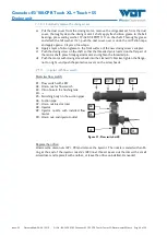
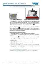
The piping to the GRANUDOS must be carefully vented. To do so, observe the prefilter
d75. If the filter's water level shows a significant drop when the pump is switched on,
turn off the GRANUDOS, open the venting screw on top of the filter and allow water
to flow back into the filter before switching the machine back on. If necessary, repeat the
process several times until the filter remains full; a few air bubbles in the upper filter area
are inconsequential.
ATTENTION!
If the pump draws air while in operation or during unmonitored
activation, the pump’s mechanical seal will run dry, overheats and
starts to leak. This can be the case with an installation above the
swimming pool level, when draining the supply line or when turning
off the filter system. In this installation scenario, the following
installation information must be observed.
1.
Install a free-flowing non-return valve in the supply line to the dosing device.
2.
Install a spring-loaded non-return valve in the dosing line to the clean water piping to
avoid the flushing tank from draining when the system is turned off. Corresponding non-
return valves are available.
3.
If it is intended or necessary to prevent an overflow when the device is turned off or in
case of a fault, install a solenoid valve 3/4” in the Inlet and a non-return valve d25 or
d32 in the drain. Check for minor pressure loss! For safe operation, a supply pressure
of more than 0.4 barg is therefore required!
4.
A venting valve that can be attached to the venting connection is optionally available.
Here, the escaping water is conducted back into the dissolving basin.


