Granudos 45/100-CPR Touch XL + Touch + S5
Dosing unit
Index: 02
Date modified: 06/06/2019
OI No.: BA SW 003-02 Granudos 45-100 CPR Touch+Touch+S5-Dosiereinheit EN.docx Page 40 of 58
5.2.5
Setting the water flow in the dissolving unit
The further proceedings are only possible when the device is turned on.
Turn the device on, using the main switch on the left side of the control unit. The booster
pump starts up. When the device is turned on, the pump is in permanent operation, except
when the pressure switch (41) or the level switch min (38) respond.
The washer in the screw connection (36) behind the injector (42) adjusts the injector’s
suction performance to the pressure conditions. If the water level in the flushing tank (46)
drops during commissioning, an orifice with a smaller bore must be inserted in the screw
connection.
If the water level rises, or if the flow switch's (47) switching body is not clearly pushed
upward, an orifice with a larger bore is required, or the orifice must be removed entirely.
An orifice with 6mm is installed by the factory; orifices with 5.5mm and 7mm are available
in the enclosed spare parts bag.
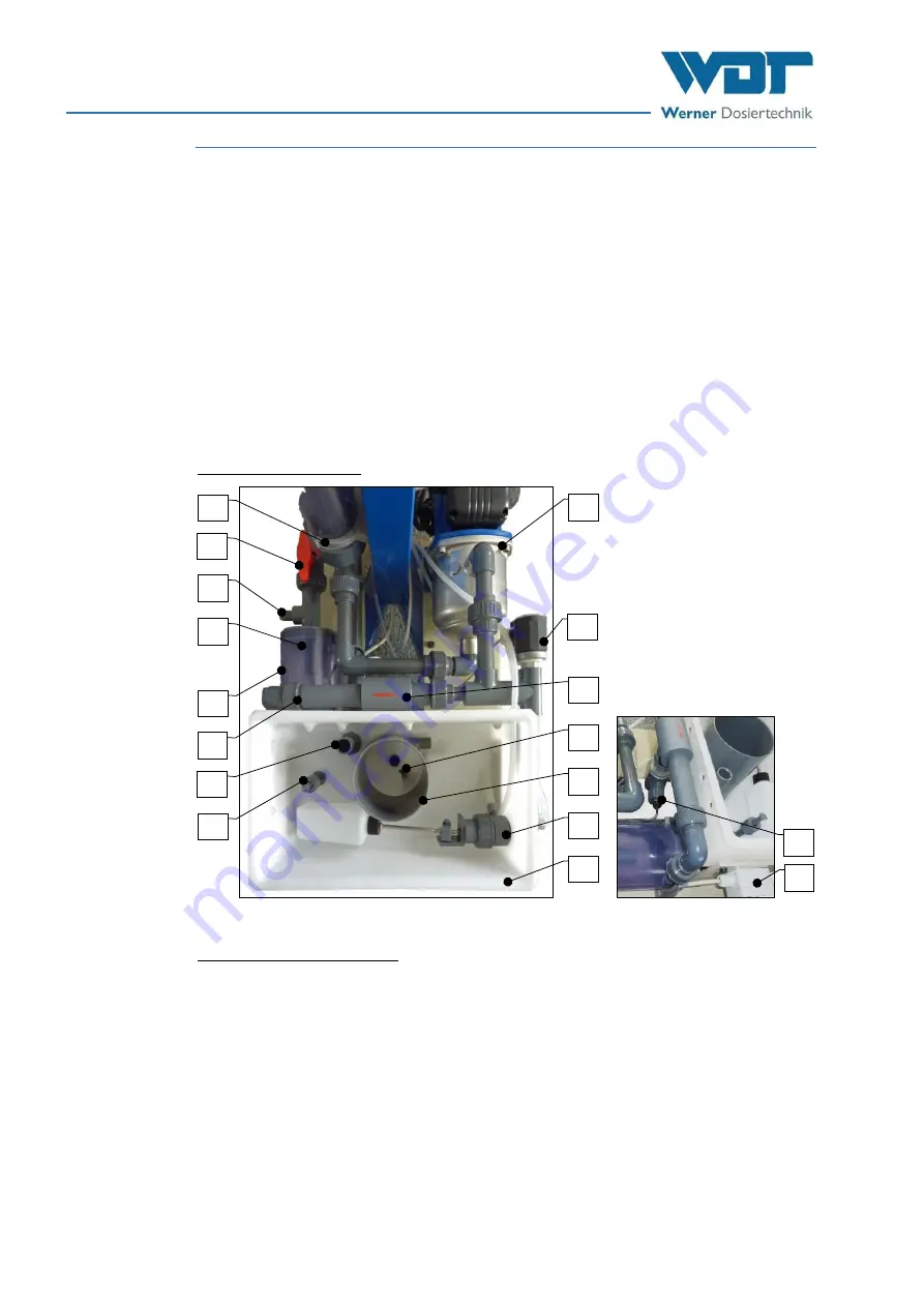
Overview dissolving unit
The dissolving unit consists of:
31.
Dirt filter d75mm
32.
Outflow ball valve for booster water
33.
Connection for manometer
34.
No chlorine switch / sensor on the
cyclone (optional, not illustrated)
35.
Dissolving and mixing cyclone
36.
Screw connection with washer
37.
Overflow flushing tank
38.
Level switch min./max. Flushing tank
39.
Booster pump (different designs)
40.
---
41.
Pressure switch
42.
Injector
43.
Dosing valve for pH reducer (acid)
44.
Flushing pipe
45.
Float control valve flushing tank Inlet
46.
Flushing tank
47.
Flow switch flushing tank
48.
Connection socket for the switches
49.
Motor for dust extraction (not
illustrated, see Figure 7)
50.
Fan for dust extraction (not illustrated,
see Figure 7)
Figure 28, Dissolving unit from above (without dust extraction)
41
42
46
45
44
39
43
32
33
34
35
37
31
38
36
48
47


