background image

Dosing unit GRANUDOS Type Flex-CPR Touch XL, 
Type Flex-Touch and Type Flex-S5 

Index: 01  Change date: 11/10/2023 

OI No.: BA SW 022-01 Granudos Flex Dosiereinheit EN.docx 

Page 26 of 68 

4


Installation 

4.1


Select the installation site 

NOTICE! 

Please pay attention to the following notices regarding the selection of the installation site: 


A freely accessible place of installation should be selected to facilitate operations and 
subsequent maintenance tasks. 


Comply with the dimensions for the floor drain and the temperature specifications for 
the ambient air and medium in accordance with the provisions in Chapter 3.4,
 on page 
22.
 No flammable vapours, dust or gases may be present in the immediate vicinity of 
the device. 


The device must not be exposed to the elements. It may not be installed outdoors. The 
system must be protected from frost and direct sunlight. 


An electricity grid connection and a drain connection must be available. 


The installation site must comply with the locally applicable accident prevention regu-
lations (from the German Accident Prevention Regulation DGUV 107-001) and should 
not be accessible to unauthorised persons. 


It must be possible to vent and aerate technical areas so that hazardous substances do 
not occur in health-hazardous concentrations (from the German Accident Prevention 
Regulations DGUV 107-001). 


A separate storage space must be available for the chemicals. 


Collecting tubs must be available for the chemical containers and the buffer tank (op-
tion). 

4.2


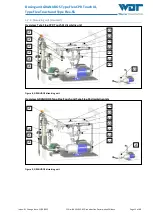
Installation instructions / installation suggestion 


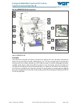
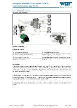
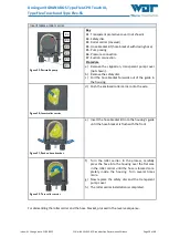
Remove transport safety devices 


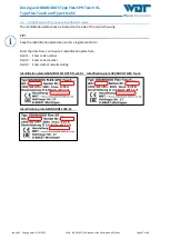
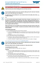
Attach warning and notice signs in accordance with the locally applicable accident prevention reg-
ulations (Germany: DGUV 107-001) at the designated positions. 

NOTICE! 

The standard GRANUDOS booster pump is not suitable for saline water (seawater/brine pools). A 
special version is available for this case. Pay attention to this when placing your order! 


Summary of Contents for GRANUDOS Flex-CPR Touch XL

Page 1: ...1 Granudos Flex Dosiereinheit EN docx Language EN Operating Instructions GRANUDOS Flex Dosing Unit Operating Instructions Part 1 without control unit for GRANUDOS Flex CPR Touch XL GRANUDOS Flex Touch...

Page 2: ...ut collecting tub only for CPR Touch XL and Touch option 20 3 2 9 Filling appliance option 21 3 2 10 GRANUDOS control unit 21 3 3 Identification of the device Identification plate 22 3 4 Technical dat...

Page 3: ...Setting the chlorine empty switch at the dosing hopper option 57 7 1 5 Replacing the dosing hose of the peristaltic pumps acid or flocculation 57 7 1 6 Cleaning the dust extraction option 59 7 2 Fault...

Page 4: ...ey have read and understood these Operating Instructions Electrical connection work may only be carried out by appropriately trained specialists 1 3 Symbols used This document uses the following types...

Page 5: ...n to prevent injuries to the front of your body due to contact with hot or chemical materials USE FOOT PROTECTION Wear approved foot protection to prevent foot injuries due to contact with hot or chem...

Page 6: ...horised modifications to the device the warranty and product lia bility will be voided 1 5 Additional information Additional information concerning specific topics such as design of the dosing perform...

Page 7: ...seawater brine pools A special version is available for this case Pay attention to this when placing your order 2 2 Safety notices Carefully read and pay attention to the operating instructions prior...

Page 8: ...SUBSTANCES Development of chlorine gas when mixing chemicals The GRANUDOS Flex dosing system doses both the calcium hypochlorite granulate and the pH reducer acid from the delivery container These su...

Page 9: ...an injector The acid dosing required for pH regulation of the swimming pool water is integrated and organised via the software and a relay system in such a way that a joint dosing of chlorine and aci...

Page 10: ...culation pump Overflow pool Heat ex changer Overflow pool Circulation pump Heat ex changer Filter Central control unit Intake pipe Flow pressure 0 2 bar Measuring and controlling Measuring and control...

Page 11: ...ock pH minus Flocculation Notice As a standard the GRANUDOS is in stalled below the pool level When the GRANUDOS is installed above the pool level non return valves must be provided in the dos ing and...

Page 12: ...ck only CPR Touch XL 04 Bracket for redox test cylinder only CPR Touch XL 05 Ball valve inlet 06 Suction lance for pH reducer acid 07 Housing 08 Collecting tub with drain option 09 Filling appliance o...

Page 13: ...of 5 or 15 kg is inserted into the housing from above and can thus be easily removed e g for maintenance work An optional filling appliance 09 is available which allows a chlorine bucket to be placed...

Page 14: ...which could lead to a dos ing blockage The dosing unit is screwed into the bottom of the dosing hopper The dosing hopper is either closed tightly with the lid or the filling appliance is used With th...

Page 15: ...s Flex Dosiereinheit EN docx Page 15 of 68 3 2 4 Dissolving unit standard Overview Type Flex CPR Touch XL dissolving unit Figure 8 GRANUDOS dissolving unit Overview GRANUDOS Type Flex Touch and Type F...

Page 16: ...tarted the chlorine granulate can be seen in the cyclone Changes in the dissolving unit s water supply that cause the dissolving unit to no longer operate properly are recorded by the level switch 48...

Page 17: ...or self closing pneumatic valves depending on the pressure situation Pay attention to the pressure loss caused by the valves during operation The Flushing tub overflow 46 conducts the nearly chlorine...

Page 18: ...the suction line Rotating rollers press the dosing hose against the housing wall which pushes the liquid in the hose out in front of the rollers while simultaneously suctioning again behind them The...

Page 19: ...the housing s interior The dust extraction is based on the water jet nozzle injector principle The flushing of the dust extraction is used for the automatic cleaning of the flushing pipe and the dust...

Page 20: ...level the dosing pump s are switched off An alarm mes sage is shown on the display the alarm output is active 4 At the buffer tank s Maximum alarm level an alarm message is shown on the display The do...

Page 21: ...e dosing hopper for maintenance pur poses see Chapter 7 1 2 or Chapter 5 2 4 2 3 2 10 GRANUDOS control unit The operation of the control unit is described in a separate set of operating instructions F...

Page 22: ...late The identification plate sticker is located on the side of the control housing TIP Keep the identification plate clean and in a legible condition Enter the data from your device s identification...

Page 23: ...st 5 bar permanently Required duct connection At least d32 Protection class IP54 Operating pressure Required inlet pressure Counter pressure Flow pressure min 0 2 bar 0 1 5 bar depending on inlet pres...

Page 24: ...plug Fuse front panel 6 3 At Hydraulic connection data Inlet d32 outflow d25 Overflow dissolving unit d25 Drain collecting tub d32 40 Inlet d25 Outflow d20 suction lance Pneumatic connection data at l...

Page 25: ...r crystal water higher than 10 Dust grain size smaller than 0 15 mm 100 mesh and content less than 1 Grain size of coarse particles larger than 2 5 mm 8 mesh and content less than 5 3 5 Transport and...

Page 26: ...n electricity grid connection and a drain connection must be available The installation site must comply with the locally applicable accident prevention regu lations from the German Accident Preventio...

Page 27: ...including space requirements without buffer tank Suggested installation GRANUDOS Flex with buffer tank Figure 17 Suggested installation including space requirements with buffer tank Dosiergr t GRANUD...

Page 28: ...ating and servicing the device 4 3 2 Buffer tank installation The buffer tank may only be operated with a suitable collecting tub Possibly a collecting tub provided On site Procedure a Place and align...

Page 29: ...pressure 0 2 bar Circulation pump Overflow pool 2 3 Solenoid valve opens when container empty GRANUDOS doses with a high dosing per formance until the container is full ap prox 10 minutes No dosing t...

Page 30: ...r Overflow pool Heat ex changer Additional pools possible Acid Dosing station for pH reducer Buffer tank for chlorine solution Measuring and controlling Circulation pump 1 Control unit for level switc...

Page 31: ...e loss should be kept at a minimum The GRANUDOS s inlet and drain are equipped with hose connections where the pressure during op eration can be measured by means of the included manometer If the coun...

Page 32: ...open metal sleeves may potentially be rusted shut Options for the water removal point Option 1 Swimming pool water directly from the pool for Flex CPR Touch XL Water removal about 200 mm below the upp...

Page 33: ...ushing tub from draining when the system is turned off see notice in the flow diagram Figure 20 corresponding non return valves are available If an overflow shall be excluded when the device is turned...

Page 34: ...s control lines to the solenoid valve d Connect the solenoid valve to the on site air supply min 5 bar 4 4 4 Installation of the overflow line for the flushing tub collecting tub and dirt filter flush...

Page 35: ...irectly touching the electronic components e g by touching a grounded part of the sys tem or by wearing an ESD antistatic wrist strap connected to ground 4 5 1 Opening and closing the housing control...

Page 36: ...in Chap ter 9 2 SIGNALS TO AND FROM OUTSIDE SEE WIRING DIAGRAMS ATTENTION External control of the inputs must be carried out in isolation Pay attention to the maximum contact current capacity of the...

Page 37: ...s piping upstream of the swimming pool filter and as close as possible to the pool ATTENTION Immersion sleeves that come into contact with the swimming pool water must be corrosion resistant Electrica...

Page 38: ...commissioning The device is delivered with defined factory settings You can find the setting values in the Operation data sheet in Chapter 9 4 ATTENTION During the installation of the piping and the e...

Page 39: ...ure a Remove the clipped on transparent pump cover not shown b Remove the safety disc c Pull the hose bracket forwards out of the guide in the housing Figure 30 Insert roller carrier d Push the enclos...

Page 40: ...ap with the suction lance from the empty acid canister place the suction lance in the collecting tub and immediately close the empty canister with the original screw cap c Lift the empty canister out...

Page 41: ...l encrustations from the dosing hopper to prevent faults during the chlo rine dosing Personal safety equipment must be put on before starting work with chemicals Protective gloves apron face protectio...

Page 42: ...ling with filling appliance Replace the granulate bucket 01 Close the filling ball valve 02 Remove the entire filling appliance turn it 180 and place it on the floor Info The filling appliance can als...

Page 43: ...nheit EN docx Page 43 of 68 05 Remove the empty granulate bucket from the cover with the tension bands and place it on the floor 06 Place the new granulate bucket in the cover with the tension bands 0...

Page 44: ...mping levers and close them securely Clicking sound 10 Shake the attachment to ensure that it sits firmly on the granulate bucket Ensure that the filling ball valve is closed 11 Turn the entire fillin...

Page 45: ...a blocked mechanical seal the booster pump s failure is inevitable c During commissioning open the ball valves at the water removal point and the dosing point as well as the ball valve inlet 05 at the...

Page 46: ...inor pressure loss For safe operation a supply pressure of more than 0 4 bar is therefore required 5 2 6 Venting the dust extraction pump option CAUTION Water may splash out when venting the pump Pers...

Page 47: ...cx Page 47 of 68 5 2 7 Setting the water flow in the dissolving unit and the pressure switch Overview Type Flex CPR Touch XL dissolving unit Figure 35 GRANUDOS Flex dissolving unit Overview GRANUDOS T...

Page 48: ...pipe union c If the water level rises or if the flow switch s 42 switch body is not clearly pushed upwards a hole washer with a larger drill hole is required or the hole washer must be removed entire...

Page 49: ...nob clockwise by 0 25 bar and wait for 6 seconds If the GRANUDOS continues to run repeat the process until the GRANUDOS stops and the Pressure too low fault indication is displayed The GRANUDOS stops...

Page 50: ...ister Pay attention to the specifications for each chemical listed in the safety data sheets Refill flocculant only CPR Touch XL See Chapter 5 2 3 Connecting the flocculant canister Pay attention to t...

Page 51: ...aning the dirt filter ATTENTION A clean dirt filter 34 is important for proper functioning A contaminated dirt filter can lead to cavitation in the booster pump causing a reduced performance and damag...

Page 52: ...only replacing the dosing screw the seal in the dust protection cover should also be renewed The sealing washers made of EPDM and felt are included in the maintenance kit s scope of delivery Required...

Page 53: ...nd close it chlorine odour d Open the connection socket on the dosing hopper and disconnect the motor cable only nec essary when changing the motor e Remove the protective caps from the attachment scr...

Page 54: ...move the old O ring 168 from the dust cover s groove insert a new O ring and apply ap prox 3 layers of Teflon tape h Spread silicon grease on the front surfaces of the dosing motor dust cover and the...

Page 55: ...osing motor Description When replacing the dosing screw without dosing motor the seal in the dust protection cover should also be renewed The sealing washers made of EPDM and felt are included in the...

Page 56: ...ing the hole washer a Loosen the union nuts 186 189 and remove the injector 187 The nozzle is sealed with an O ring at the end of the injector nozzle s 188 inner thread b Pry out this washer with a sm...

Page 57: ...at the control unit with a 6 second delay If the switch does not react to the adjustment potentiometer or if the adjustment screw has been destroyed a new switch must be installed Procedure for adjust...

Page 58: ...d The markings must be centred at the front see picture Overview Individual components of the hose bracket kit Figure 45 Hose bracket kit Procedure a Disassemble the hose kit see Chapter 5 2 1 page 38...

Page 59: ...aning the dust extraction option CAUTION Due to the excessive chlorine dust personal safety equipment must be put on prior to start ing the work Protective gloves apron face protection Overview dust e...

Page 60: ...ring cell block in Chapter Fault removal For GRANUDOS Touch Operating Instructions GRANUDOS Touch Control Unit No BA SW 010 in Chapter Fault removal For GRANUDOS S5 Operating Instructions GRANUDOS S5...

Page 61: ...ttered chlorine grains f Remove the roller carrier from the peristaltic pumps in order to relieve the dosing hose see Chapter 7 1 g Thoroughly clean all parts of the GRANUDOS Flex h If there is a risk...

Page 62: ...t GRANUDOS Type Flex CPR Touch XL Type Flex Touch and Type Flex S5 Index 01 Change date 11 10 2023 OI No BA SW 022 01 Granudos Flex Dosiereinheit EN docx Page 62 of 68 9 Documents 9 1 Declaration of c...

Page 63: ...spective Operating Instructions for the control unit For GRANUDOS CPR Touch XL Operating Instructions CPR Touch XL Measuring and Control Unit No BA MR 001 in Chapter 9 2 For GRANUDOS Touch Operating I...

Page 64: ...Type Flex Touch and Type Flex S5 Index 01 Change date 11 10 2023 OI No BA SW 022 01 Granudos Flex Dosiereinheit EN docx Page 64 of 68 9 3 Commissioning protocol The commissioning protocol is included...

Page 65: ...e operation data sheet can be found in the respective Operating Instructions for the control unit For GRANUDOS CPR Touch XL Operating Instructions CPR Touch XL Measuring and Control Unit No BA MR 001...

Page 66: ...L Type Flex Touch and Type Flex S5 Index 01 Change date 11 10 2023 OI No BA SW 022 01 Granudos Flex Dosiereinheit EN docx Page 66 of 68 9 5 Maintenance protocol The maintenance protocol is included wi...

Page 67: ...0 Pump casing Sa 14140 0 Roller carrier Sa blue 13039 X 0 Hose kit 3 2x1 6 Ph Sa 2x 13413 X 0 Suction set GR Flex red 3 m 30393 0 Dosing valve acid GR 15099 X 0 Maintenance kit for acid valve 3 8 KF...

Page 68: ...nd Flex S5 Personal notes _________________________________________________________ _________________________________________________________ _________________________________________________________...

Page 69: ...ult display 1 8 Adjust the pressure switch 1 9 Adjust the water level in the flushing tub 1 10 Check the flow switch Close ball valve drain dosing stops fault display open the ball valve again 1 11 Ch...

Page 70: ...7 1 Insert the cleaning beads 7 2 Install electrodes 7 3 Open ball valve at measuring cell intake set measuring cell flow 7 4 Set control parameters if necessary 8 Other 8 1 Note down the inlet press...

Page 71: ...ving unit 1 1 Check level switch 6 1 2 Check the pressure switch adjust if neces sary 6 1 3 Check the function of the flow switch 6 1 4 Renew the floating valve diaphragm and the conical seal 12 1 5 C...

Page 72: ...6 5 3 Renew dosing hose 12 5 4 Renew the seals of the flocculation dosing valve on site 12 6 Buffer tank optional 6 1 Check the function of the level switches 4x buffer tank 1x collecting tub 6 6 2 C...

Page 73: ...Pr fbericht etc WDT Wartungsprotokolle WP WDT WP 080 EN GR Flex CPR Touch XL FO 00 docx Key F with each granulate filling 1 monthly 3 every 3 months 6 every 6 months etc work completed Page 3 of 3 Add...

Page 74: ......

Page 75: ...ng tub 1 9 Check the flow switch Close ball valve drain dosing stops fault display open the ball valve again 1 10 Check level switch min max for flushing tub Switch body up dosing stops fault display...

Page 76: ...management ISO 9001 MS Originale Formuale Pr fbericht etc WDT Inbetriebnahmeprotokolle IP WDT IP 079 EN GR Flex Touch FO 00 docx Page 2 of 2 Additional remarks Commissioning and instruction carried ou...

Page 77: ...nit 1 1 Check level switch 6 1 2 Check the pressure switch adjust if necessary 6 1 3 Check the function of the flow switch 6 1 4 Renew the floating valve diaphragm and the conical seal 12 1 5 Check an...

Page 78: ...2 4 3 Exchange the disconnect lever of the sole noid valve 12 5 Buffer tank option 5 1 Check the function of the level switches 4x buffer tank 1x collecting tub 6 5 2 Clean the buffer tank with water...

Page 79: ...d device stops fault display 1 7 Adjust the pressure switch 1 8 Adjust the water level in the flushing tub 1 9 Check the flow switch Close ball valve drain dosing stops fault display open the ball val...

Page 80: ...management ISO 9001 MS Originale Formuale Pr fbericht etc WDT Inbetriebnahmeprotokolle IP WDT IP 078 EN GR Flex S5 FO 00 docx Page 2 of 2 Additional remarks Commissioning and instruction carried out b...

Page 81: ...1 1 Check level switch 6 1 2 Check the pressure switch adjust if neces sary 6 1 3 Check the function of the flow switch 6 1 4 Renew the floating valve diaphragm and the conical seal 12 1 5 Check and a...

Page 82: ...he suspensor including the injector and flushing pipe 2 4 2 Check the drill holes of the outlet connec tion for contamination and clean them 2 4 3 Exchange the disconnect lever of the sole noid valve...

Reviews: