background image

Summary of Contents for Solfog V2

Page 1: ...Item no 26143 Language EN Operating and installation instructions Brine fog making Type Solfog V2 ...

Page 2: ...chnical data 11 3 5 Transport storage 12 4 Assembly 13 4 1 Selecting the place of installation 13 4 2 Assembly information installation suggestion 13 4 3 Mechanical installation 14 4 4 Hydraulic installation 14 4 5 Electrical installation 15 5 Initial operation 16 5 1 Commissioning comments 16 5 2 Initial operationworks 16 5 2 1 Insert the roller carriers into the fragrance pump 16 5 2 2 Perform d...

Page 3: ...4 9 4 Operating data sheet 35 9 5 Maintenance protocol 36 9 5 1 Disinfection protocol 37 9 6 Spare parts list wearing parts list consumables list 38 10 Appendices 39 Imprint All rights reserved Copyright by WDT Werner Dosiertechnik GmbH Co KG Version see footer Publications of any kind and translation into other languages also of excerpts is only permitted with the explicit approval of WDT Werner ...

Page 4: ...nstructions may work on the system Electrotechnical connection work may only be performed by appropriately trained specialist staff 1 3 Symbols used The following types of safety instructions and general instructions are used in this document DANGER DANGER indicates a safety instruction that must be adhered to at the risk of death or severe injury CAUTION CAUTION indicates a safety instruction tha...

Page 5: ...provide a warranty for half a year on those parts Our ERP program requires an invoice for each delivery also for warranty services Customers will receive a credit note after returning the faulty part and its inspection as required Please return goods within 14 days Costs for consequential damage and costs resulting from handling warranty claims are excluded Warranty claims are not valid when the d...

Page 6: ...ng are adhered to Take note of the warning information on the device Note for electrical tension Note for corrosion resistance 2 2 1 Handling of chemicals risks to persons and the environment Important information on the handling of chemicals and fragrances is provided in the safety data sheets of the chemicals manufacturers With the brine fog maker a fragrance can be added to the brine fog The fr...

Page 7: ...juries to persons or risks to the environment It is therefore necessary to perform all work with great care In emergencies relating to the handling of chemicals you can contact a Poison Emergency Call Centre Emergency call number Poison Emergency Call Munich or any other poison centre Telephone 49 89 19240 2 2 2 Protective measures and behavioural rules ATTENTION Please adhere to the locally appli...

Page 8: ...maker makes a fog of the brine or also water by means of an ultrasonic fog maker The brine is supplied to the cabin by means of an air flow generated by the fan When the ultrasonic fog maker starts at the same time by means of a hose pump 04 there will be a backfeed of brine in the fog maker tank In this way the used brine is changed and at the same time the ultrasonic fog maker is cooled Optional...

Page 9: ... Cable ultrasonic fog maker 19 Fog maker tank 20 Support fog maker tank 21 Ultrasonic fog maker 22 Installation plate 3 2 1 Control unit The control unit has a control housing 02 of protection class IP64 All electronic components are installed in it At the control unit the service parameters can be adjusted on a LCD display with 5 lines and 3 operation buttons 3 2 2 The dosing unit for brine solut...

Page 10: ...e can be blown into the room Therefore the fragrance tank 15 must be filled to the marking maximum 50ml with a fragrance for fragrancing the room and a filter star must be installed The fan 13 blows the evaporated fragrance by means of a reflux valve 14 into the fog maker tank There the fragrance is mixed with the brine fog and is blown into the connected cabin 3 3 Identification of the device nam...

Page 11: ...Empty weight operating weight 11kg 16kg Connection data Inlet water Connection fog maker pipe 40mm Electrical connection 230VAC 50Hz 50W safety connector Main fuse Microfuse 20x6mm 2A with time lag Nominal pressure operating pressure Max 1 7 barg Operating data Evaporation power Max 0 5 l h Hose pump 24VDC Control unit for Solfog 230VAC Medium temperature 5 to 35 C Environmental temperature in uti...

Page 12: ... original packaging Careful handling must be ensured The roller carrier of the dosing pump is not installed during transport and storage This prevents deformation of the hose Storage of fragrances chemicals DANGER The safety data sheets of the fragrance manufacturers have to be considered with regard to storage The following points must be considered among others Fragrances and the brine solution ...

Page 13: ...ply and extraction are recommended for the installation room 4 2 Assembly information installation suggestion The Solfog V2 is mounted on a wall in the utility room The pipe to the cabin should be as short as possible maximum 4m Consider the space required for operation and maintenance of the device described in Section 3 4 Technical data ATTENTION The brine fog maker is not intended for installat...

Page 14: ...ncluded in the scope of delivery Assemble piping Search an appropriate place for the fog inlet in the cabin Drill a 40 mm big opening in the cabin wall Tube the fog conduct from the brine fog maker to the cabin with d 40mm The fog maker pipe must be installed with a slope of 1cm for each 1m line length 1 to the fog maker device The conduct must have a maximum length of 4m In the conduct maximum 5 ...

Page 15: ...Additional works for the connection to an external control system Connection of the external control signal 230VAC on the terminal SL3 or 24VDC on the terminal SL4 according to the supplied terminal plan Connection of the potential free accumulative error message on the ZLT central control system on the terminal SL5 Reset to factory settings Disconnect the device on the main switch To avoid the pr...

Page 16: ...e during commissioning and enter these values into the operating data sheet shown in Section 9 4 To reset the device to the factory settings see section 4 5 Reset to factory settings 5 2 Initial operationworks Filling and starting the brine fog maker Ensure that the device is appropriately installed and connected Follow the order of the start up works 5 2 1 Insert the roller carriers into the frag...

Page 17: ...en completed Disassembly of the roll carrier and of the hose support in reverse order 5 2 2 Perform disinfection Explanation of the operation Next to the LCD display there are 3 operation buttons With these buttons you can scroll in the menu Navigation upwards The arrow key can be used to move upwards or to adjust numerical values Enter key The enter key opens the sub menu selected or takes the us...

Page 18: ...rt with the Enter button 3 Connect politainer Fill the empty supplied 1 liter brine politainer with 0 5 liter water add the supplied disinfection tablet SOLDOS art nr 19871 and let it disintegrate Take the politainer from the console and unscrew the original lock from the politainer Pull the politainer connection for SOLDOS from the fitting of the suction conduct Screw the politainer connection on...

Page 19: ...sinfection solution in a synthetic container or evacuate directly in the sewer system CAUTION Guarantee that there is nobody in the corresponding cabin The nozzle adapter with hose is connected to the fog nozzle in the cabin so that the escaping liquid can be collected in a container or can be evacuated directly in the sewer system Confirm the message with Enter 51 52 Figure 15 Connection for disi...

Page 20: ...tainer with the remaining disinfection solution rinse and store for the next disinfection Disassembly empty and rinse the fog container 19 with potable water and put the empty tank again in its place Confirm the message in the display with Enter ATTENTION Document each disinfection in the disinfection report in section 9 5 1 CAUTION When a fault is produced during the disinfection it must be remed...

Page 21: ...kg and hold it with the lock upwards and open the lock of the brine politainer Attention the politainer is now open Then you screw the politainer connection on the open brine politainer Now you insert the connection plug into the connection sleeve of the politainer connection Now the politainer is closed again Turn the closed politainer 180 upside down on the console 10 so that the yellow belt rin...

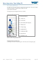
Page 22: ...ice After a standstill time of more than 7 days first perform again a disinfection at the beginning of the service After a standstill time of 7 days or less you can take the device into service as described in section 5 2 3 Filling and starting the brine fog maker The operation can be started once all commissioning preparations have been completed Switch on the device at the main switch if that ha...

Page 23: ... can scroll in the menu with the 3 operation keys The menu functions are described in the next section If the black square appears in the display then the correct level in the fog maker tank has been reached If the round key symbol appears in the display then the device has been adjusted on key service If the point in the round key symbol appears then the key service is activated By pressing a ran...

Page 24: ... control determines the dosing and pausing times The control does not react on the button signal 3 Button service In the button service the evaporation is started through the buttons in the cabin In this service mode the fog maker can also be operated with an external signal instead of the button The device is working as long as the signal is present 6 3 6 Fan Ventilator Adjust here the desired fa...

Page 25: ...ation is started and all error messages are retrieved Start the device test with the Enter button Cancel with the ENTER button 6 3 11 Pump test The hose pump is activated for the time shown Start the test with the ENTER button Cancel with the ENTER button 6 3 12 Fan test The fan is activated for the time shown Start the test with the ENTER button Cancel with the ENTER button 6 3 13 Contrast The co...

Page 26: ... change the brine politainer see section 5 2 3 page 20 6 4 2 Refill change fragrance 13 Fan 81 Filter star 15 Fragrance container 82 Filling height marking 50ml 1 Screw the fragrance tank 15 out of the aluminium holder if necessary clean it or use a new fragrance tank 2 Place a clean filter star 82 in the fragrance tank 3 Fill the desired fragrance in the fragrance tank until the marking max 50ml ...

Page 27: ...liminated DANGER DUE TO HIGH VOLTAGE The device must be switched off and secured against re operation before any electrical work is carried out 7 1 1 Maintenance works at the control casing general ATTENTION The electronic components of the devices are sensitive to electrostatic discharge The generally known precautions regarding ESD sensitive devices must be adhered to when handling these devices...

Page 28: ... in due time and to change the dosing hose The dosing hose must be changed at least every 6 months Components of the hose dosing pump Figure 22 Hose dosing pump spare parts Changing the hose set and roller carrier see description in Section 5 2 Commissioning work Insert roller carrier at the fragrance pump The hose pump Type Sa 31 Pump cover 32 Lock washer 33 Hose holder with dosing hose 34 Roller...

Page 29: ... in order to exchange the dosing hose Take care not to damage the hose nipples 3 Push the new dosing hose onto the hose nipples so that the markers at the hose ends are in front This ensures that the hose is not twisted 4 Fasten the hose ends with the hose ties and cut off the protruding parts of the hose ties 5 Removing the hose set see Section 5 2 Commissioning work The individual parts of the h...

Page 30: ...ve Check exchange the pump hose Fault indication 4 Push button cycle not active Wrong operation mode selected Select correct operation mode The device cannot be switched on Main fuse defective Main switch defective Power supply interrupted Check exchange the fuse Check main switch Check the power supply Device without function Wrong setting Main fuse defective Control board defective Plug pulled o...

Page 31: ... from the institution responsible for disposal at your place of operation When this is not possible dispose of them as special waste 8 2 Shutting down If the system is put out of service for more than 28 days disconnect the device on the main switch The fog maker container must be manually emptied and cleaned when the device is shut down for more than 28 days The fog maker head must be dried with ...

Page 32: ...Brine fog maker Type Solfog V2 Index 01 Change date 12 12 2017 Operating instructions no BA DW 018 01 Solfog V2 EN docx Page 32 of 39 9 Documents 9 1 Declaration of conformity ...

Page 33: ...ice Fuses circuit board Reset on factory settings Dip switch SW2 Supply 230V AC Plug Power supply fog maker Art 20340 Adjusted to 13VDC 1 brown Plug 3 white 1 red 1 white 2 black 2 brown Level switch Ultrasonic fog maker Hose rupture protection device Brine pump External control 230VAC option Fault indication external Soldering point Coding of plug connector External control Pot free option Cable ...

Page 34: ...18 01 Solfog V2 EN docx Page 34 of 39 9 3 Commissioning protocol instruction This protocol is to be completed by the commissioning technician All warranty claims expire when no completed and signed commissioning protocol is available The commissioning protocol is included in the documents attached ...

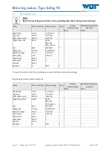
Page 35: ... Filling time 150 sec 150 300 sec Empty message 15 sec 1 120 sec Flow pump 5 sec 1 20 sec Device test 20 sec Pump test 20 sec Fan test 20 sec Contrast 8 0 15 1 To reset the device to the factory settings see section 4 5 Reset to the factory settings Operating data sheet master template Menu Factory settings Setting ranges Step During commissioning Optimised during the operation Date Date Break tim...

Page 36: ...lfog V2 EN docx Page 36 of 39 9 5 Maintenance protocol Perform the maintenance work listed in order to retain the validity of your warranty The maintenance protocol is included in the documents attached ATTENTION Do not clean the fog maker membrane with sharp objects use only a soft cloth or paper tissues ...

Page 37: ...disinfection must be performed as described in section 5 2 2 this disinfection must be documented in the disinfection report If the device is not used for more than 7 days this must be documented as well After a standstill of more than 7 days a disinfection must be performed as well at the beginning of the operation Disinfection putting out of service Completed Date Name Length of the fog conduct ...

Page 38: ... motor SA 24 VDC 13557 Installation screws set 17067 Control Fuse bag 2x2A round D 8mm 21388 Fuse bag 2x315mA round D 8mm 23625 Control housing complete 25979 Control board NT 35 with program brine fog maker 25346 Display HMI MP3 NT 35 25364 Mains switch 21468 Wearing parts list Device Description Item no WDT Hose set SA 13413 Roller carrier for hose pump blue 13039 List of consumables Device Desc...

Page 39: ...Brine fog maker Type Solfog V2 Index 01 Change date 12 12 2017 Operating instructions no BA DW 018 01 Solfog V2 EN docx Page 39 of 39 10 Appendices Commissioning protocol Maintenance protocol Own notes ...

Page 40: ......

Page 41: ...nstructions Section 5 2 2 was performed 1 6 Device filled and started according to the operating manual part 5 2 3 1 7 Adjustments performed service mode selected and inserted in the operation data sheet under part 9 4 1 8 All test programmes checked 1 9 Brine mist maker started 1 10 Device checked for correct operation 2 Other 2 1 Operating instructions discussed and handed over 2 2 Operating and...

Page 42: ......

Page 43: ... 5 2 2 at least every 28 days X 1 2 Clean the mist maker membrane with a soft cloth 1 1 3 Grease the O ring of the mist tank 1 1 4 Check hose pump for function and leak tightness 1 1 5 Check the device for tightness and visual checking 3 1 6 Perform test programmes 3 1 7 Exchange hose set only use WDT original part 6 1 8 Clean the device 6 1 9 Check electrical cabling 6 1 10 Replace filter star 12...

Reviews: