Tele Indication, Type 10” Touch-V1
Index: 00
Date modified: 01/08/2017
OI No.: BA MR 002-00 Fernanzeige V1 EN.docx
Page 8 of 25
4
Installation
4.1
Select the installation site
The installation site must have the following properties:
1.
Do not operate the device in direct sunlight, near heat sources or in a humid place.
2.
Keep the device away from water and other liquids.
3.
An electrical power connection with a mains socket must be available. It should be possible to switch the
socket from the technical room.
4.
The data cables of the individual devices must be connected to the control cabinet and the router according
to the function diagram.
5.
A data cable must be available from the router to the installation location.
4.2
Installation instructions (assembly suggestion)
The remote display is mounted on the wall or on a suitable stand at the desired place of installation.
ATTENTION!
The remote display must not be exposed to any brine concentration!
The remote display must not be exposed to moisture or humidity!
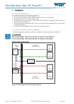
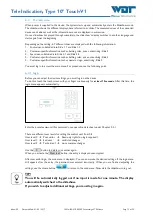
Remote display function diagram
Figure 3, Tele Indication 10” Touch-V1 function diagram
Funktionsschema Fernanzeige
Fernanzeige
Typ 10" Touch- V1
für Pool & Wellness
Technikraum
Gerät 1
Gerät 2
Gerät 1
Gerät 2
Schaltschrank
Router
z. B.
Steuerung
Hydro-Pool
z. B.
Steuerung
Relax - Pool
z. B.
Sauna -
Steuerung
z. B.
Dampfbad -
Steuerung
RJ 45
RJ
45
ma
x.
8
1
2
3
4
5
6
7
8
8
7
6
5
4
3
2
1
Pool Bereich
max. 8 Pool- Werte
Wellness Bereich
max. 8 Wellness- Werte
Technical
room
Pool area
max. 8 pool values
Device 1
e.g.
Control unit
Hydro pool
Spa area
max. 8 spa values
Device 1
e.g.
Control unit
Hydro pool
Device 1
e.g.
Control unit
Hydro pool
Device 1
e.g.
Control unit
Hydro pool
Router/
Switch
Remote display
Type 10” Touch V1
for pool&spa
Control
cabinet
RJ
45
m
in
. C
AT
6
m
ax
. 8


